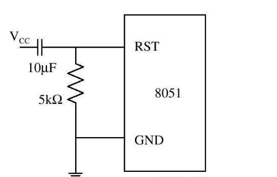
The MCU reset circuit is composed of capacitors connected in series with resistors. From the figure and the nature of "capacitor voltage cannot change abruptly", we can know that when the system is powered on, the RS T pin will appear at a high level, and this high level continues The time is determined by the RC value of the circuit, and the capacitor is generally 10~30uF.
The working principle of the MCU reset circuit is that the resistor charges the capacitor, and the voltage of the capacitor rises slowly until VCC. When VCC is not reached, the reset pin of the chip is approximately low, so the chip resets. When it is close to VCC, the reset pin of the chip is close to high level, so the chip resets Stop reset, reset is complete.
After the clock circuit starts to work, the high level of more than 24 clock oscillation pulses is applied to the RST reset pin of the single-chip microcomputer, and the single-chip microcomputer can be reset. When the RST pin jumps from high level to low level, the microcontroller starts executing the program from address 0000H.
The reset circuit of the single-chip microcomputer can have power-on reset, manual power-on reset, watchdog reset and some complex reset circuits. In practical applications, an external reset circuit is generally used to reset the microcontroller. At this time, keeping the RST pin at a high level for more than 10ms can ensure that the microcontroller can be reset reliably.
SCM power-on reset circuit diagram (1)
The following delay reset circuits are all formed by connecting an RC branch circuit charging time to the RST pin of the microcontroller.
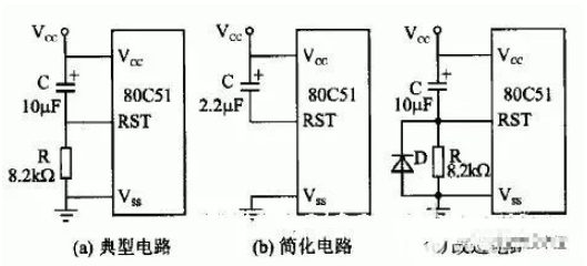
A typical reset circuit is shown in Figure (a), where the resistance and capacitance values are provided in the original manual. Figure (b) is a simplified reset circuit, and Figure (c) adds a diode D on the basis of Figure (a), which is helpful for the rapid discharge of capacitor C and prepares for the next power-on reset delay.
After a series of delays, the MCU starts to enter the normal program running state according to the operating frequency of the clock source.
SCM power-on reset circuit diagram (2)
The reset circuit consists of two parts: button reset and power-on reset.
(1) Power-on reset: STC89 series single-chip microcomputer and high-level reset, usually connect a capacitor to VCC on the reset pin RST, and then connect a resistor to GND, thereby forming an RC charge-discharge circuit to ensure that the single-chip microcomputer is powered on. When the RST pin has a high level for enough time to reset, and then returns to the low level to enter the normal working state, the typical values of this resistor and capacitor are 10K and 10uF.
(2) Button reset: Button reset is to connect a switch in parallel on the reset capacitor. When the switch is pressed, the capacitor is discharged and RST is also pulled to a high level, and due to the charging of the capacitor, it will maintain a high level for a period of time. Reset the MCU.


