Impedance of the RC series circuit
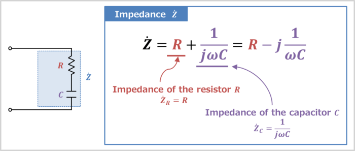
An RC series circuit (also known as an RC filter or RC network) is an electrical circuit consisting of a resistor R and a capacitor C connected in series, driven by a voltage source or current source.
The impedance Z˙R of the resistor R and the impedance Z˙C of the capacitor C can be expressed by the following equations:
Z˙RZ˙C==R−jXC=−j1ωC=1jωC
,where ω is the angular frequency, which is equal to 2πf, and XC(=1ωC) is called capacitive reactance, which is the resistive component of capacitor C.
The impedance Z˙ of the RC series circuit is the sum of the respective impedance, and is as follow:
Z˙===Z˙R+Z˙CR+1jωCR−j1ωC
Magnitude of the impedance of the RC series circuit
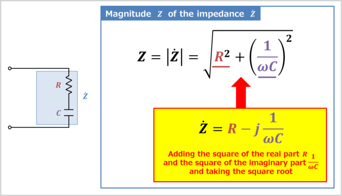
The magnitude Z of the impedance Z˙ of the RC series circuit is the absolute value of "Z˙=R−j1ωC".
In more detail, the magnitude Z of the impedance Z˙ can be obtained by adding the square of the real part R and the square of the imaginary part 1ωC and taking the square root, which can be expressed in the following equation:
Z=|Z˙|=R2+(1ωC)2−−−−−−−−−−−√
The magnitude ZR of the impedance of the resistor R and the magnitude ZC of the impedance of the capacitor C are expressed as follows:
ZRZC==|Z˙R|=R2−−−√=R|Z˙C|=(1ωC)2−−−−−−−√=1ωC
Supplement
Some impedance Z symbols have a ". (dot)" above them and are labeled Z˙.
Z˙ with this dot represents a vector.
If it has a dot (e.g. Z˙), it represents a vector (complex number), and if it does not have a dot (e.g. Z), it represents the absolute value (magnitude, length) of the vector.
Vector diagram of the RC series circuit
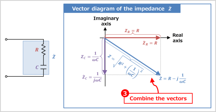
The vector diagram of the impedance Z˙ of the RC series circuit can be drawn in the following steps.
How to draw a Vector Diagram
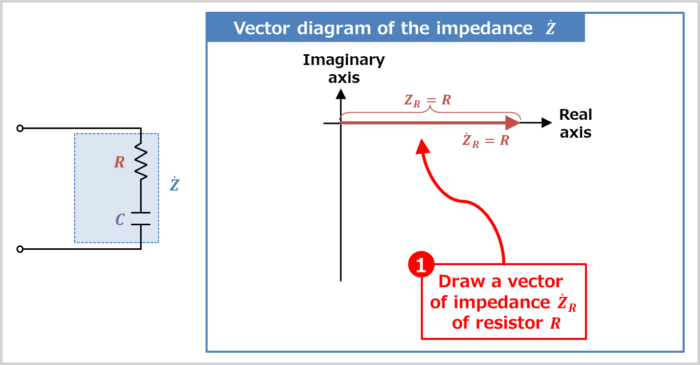
- Draw a vector of impedance Z˙R of resistor R
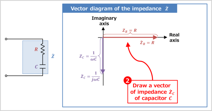
- Draw a vector of impedance Z˙C of capacitor C
- Combine the vectors
Let's take a look at each step in turn.
Draw a vector of impedance Z˙R of resistor R
The impedance Z˙R of the resistor R is expressed as "Z˙R=R".
Therefore, the vector direction of the impedance Z˙R is the direction of the real axis. How to determine the vector orientation will be explained in more detail later.
The magnitude (length) ZR of the vector of the impedance Z˙R is "ZR=|Z˙R|=R".
Draw a vector of impedance Z˙C of capacitor C
The impedance Z˙C of the capacitor C is expressed as "Z˙C=−j1ωC".
Therefore, the orientation of the impedance Z˙C vector is 90° clockwise around the real axis (with "−j", it rotates 90° clockwise). How to determine the vector orientation will be explained in detail later.
The magnitude (length) ZC of the vector of the impedance Z˙C is "ZC=|Z˙C|=1ωC".
Combine the vectors
Combining the vector of "impedance Z˙R of resistor R" and "impedance Z˙C of capacitor C" is the vector diagram of the impedance Z˙ of the RC series circuit.
The magnitude (length) Z of the vector of the impedance Z˙ is "Z=|Z˙|=R2+(1ωC)2−−−−−−−−−−−√".
Supplement
The magnitude (length) Z of the vector of the synthetic impedance Z˙ of the RC series circuit can also be obtained using the Pythagorean theorem in the vector diagram.
Vector orientation
Here is a more detailed explanation of how vector orientation is determined.
Vector orientation
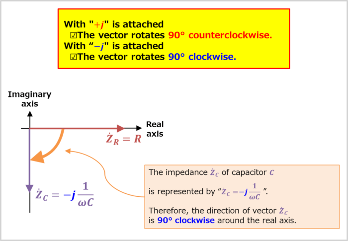
When an imaginary unit "j" is added to the expression, the direction of the vector is rotated by 90°.
-
With "+j" is attached
- The vector rotates 90° counterclockwise.
-
With "−j" is attached
- The vector rotates 90° clockwise.
The impedance Z˙C of capacitor C is represented by "Z˙C=−j1ωC". Therefore, the direction of vector Z˙C is 90° clockwise around the real axis.
Impedance phase angle of the RC series circuit
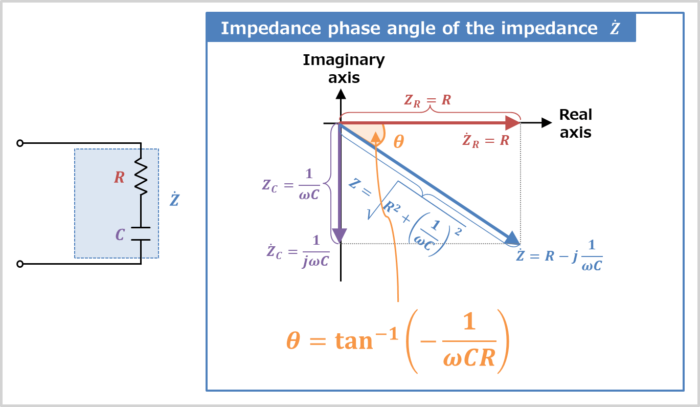
The impedance phase angle θ of the RC series circuit can be obtained from the vector diagram.
The impedance phase angle θ of the RC series circuit is expressed by the following equation:
tanθ⇔θ==−1ωCRtan−1(−1ωCR)
Summary
In this article, the following information on "RC series circuit was explained.
