
Running a PCB impedance calculation without a field solver can be achieved using various approximate methods and online calculators. Here's a systematic approach to performing PCB impedance calculations without a field solver: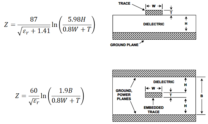
-
Differential Pair Impedance Calculation:
- Use the differential pair impedance formulas for microstrip and stripline configurations to calculate the impedance of differential pairs based on trace width, spacing, substrate material properties, and dielectric constants. Many online calculators provide tools for this purpose.
-
Microstrip and Stripline Impedance Calculations:
- For single-ended traces, employ the well-established approximations and equations for microstrip and stripline impedance based on trace width, dielectric constant, and substrate thickness. Numerous online calculators and reference materials are available for these calculations.
-
Embedded Microstrip Impedance Calculation:
- Utilize approximate equations for embedded microstrip configurations to estimate the impedance of traces embedded within PCB layers. This involves considering the thickness and dielectric properties of the layers surrounding the trace.
-
Coplanar Waveguide Impedance Calculation:
- Calculate the impedance of coplanar waveguides using simplified formulas that take into account trace width, gap, substrate properties, and metal thickness. These calculations can be performed without the need for a full field solver.
-
Online Calculators and Reference Materials:
- Leverage available online tools, calculators, and reference materials that provide impedance formulas and approximations for different transmission line configurations. Verify the accuracy of the calculators by cross-referencing the results with known standards and design rules.
-
Guidelines and Design Rules:
- Refer to impedance control guidelines and design rules provided by PCB manufacturers and substrate material vendors. These guidelines often include recommended trace geometries and dimensions to achieve specific impedance values.
-
Simulation Tools with Built-In Calculators:
- Utilize PCB design software and simulation tools that offer built-in impedance calculators and approximation methods to estimate trace and transmission line impedances based on user-input parameters.
-
Cross-Verification and Validation:
- Cross-verify calculated impedance values with known standards, design rules, and industry best practices to ensure the accuracy of the calculated values and to fine-tune the calculations as needed.
- Cross-verify calculated impedance values with known standards, design rules, and industry best practices to ensure the accuracy of the calculated values and to fine-tune the calculations as needed.
While field solvers provide highly accurate impedance calculations, the aforementioned methods and tools offer valuable alternative approaches for estimating PCB impedance without access to a field solver. These methods can be effective for preliminary design assessments and for achieving reasonable impedance approximations in many practical scenarios.