The project I am presenting to you today, ESP32lights , is a smart lighting control unit based on the esp32 chip.
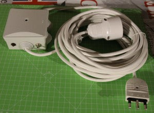
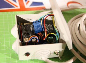
Through ESP32lights it is possible to turn on / off a load (I use it for Christmas lights ...)
[checklist]
- manually
- according to an hourly schedule
- according to the brightness
[/checklist]
ESP32lights connects to the home wifi network, is managed entirely via browser and is optimized for mobile devices ( responsive interface based on jQuery Mobile).
Components
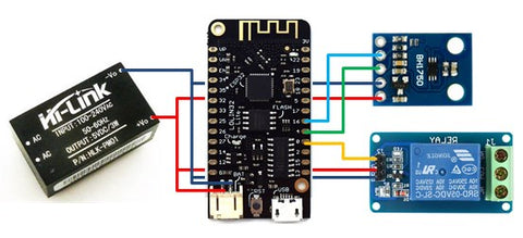
The heart of the ESP32lights control unit is the Wemos L olin32 Lite development board . One of the digital pins of the card is connected to a relay module , which controls the load. Two digital pins, assigned to the first i2c controller of the esp32 chip, are instead connected to the BH1750 brightness sensor . The power supply to all the devices of the control unit is finally supplied by the Hi-Link HLK-PM01 module which converts the 220V AC of the network into 5V DC without the need for external components:
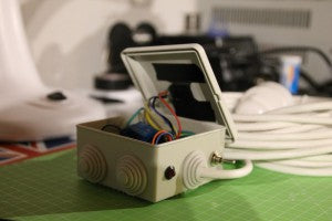
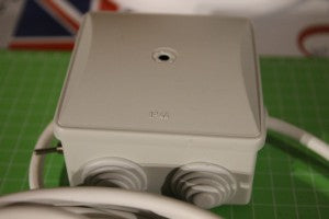
All the components are placed in a wateright container , so that the control unit can also be placed outside:
Programming
The program running on the esp32 devboard is available in my Github repository.
In one of the following paragraphs I will illustrate how it works. If you simply want to build your ECU, you can program the firmware as follows:
1) clone my repository in a local folder on your PC (you must have the esp-idf development environment installed).
2) configure the parameters of your wifi network and time zone via menuconfig :

3) compile and program the firmware :
make flash
4) store the SPIFFS partition in the flash (use your COM port and the path where you saved the img file):
python $IDF_PATH/components/esptool_py/esptool/esptool.py --chip esp32 --port COM15
 --baud 115200 write_flash --flash_size detect 0x180000 /home/esp32lights.img
If everything has been done correctly, connecting in serial ( make monitor ) to the development board the following output should appear:

Usage
ESP32light provides an HTTP interface through which it is possible to enter programming (hourly or based on a light intensity threshold) or manually control the switching on and off of the load connected to the control unit.
The interface can be viewed by connecting (from a PC or smartphone ) to the address http: // <esp_ip> (the IP address of the card is visible from the serial output as shown in the previous paragraph).
The interface is divided into 3 tabs , one for each operating mode:

The status bar displays the current operating mode:

If you are interested in the project, you can mail to lisa.wang@pcb-hero.com
