
Components Required
- Esp32 Module
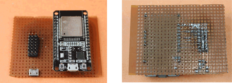
- Zero PCB
- Female & Male Header Pins
- Jumper Wires
- Micro-USB Female Jack
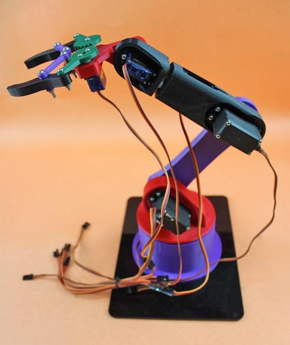
Getting 3D Printed Robo Arm & Assembly
Assembling the Robo Arm is a straightforward process as it is entirely 3D printed in small parts. With a few components and simple instructions, the entire arm can be easily put together. The required components are:
- 3* MG995 Servos (180-degree rotation)
- Few Nuts and Bolts of different Sizes.
The screws and horns for installing Servos are available in the servos kit, and the rest part can be assembled easily by Nuts and Bolts, which you will get easily inside the whole Robotic Arm Kit from your vendor.
The Assembly process requires a little bit more attention for the perfect fitting of the servo’s arms with their correct rotational angle of 180 degrees. You can refer to the blog and YouTube videos of How To Mechatronics by using the link.
You will find the easy and simplest way to assemble the whole Arm there. Also, you will get the link for the STL files for your 3d design model, if you wish to design it from Scratch.
The below image gives an idea about the looks of the final assembled product.
Circuit Diagram for ESP32 based Robotic Arm
The circuit connections are pretty simple, just connect each servo +ve & -ve terminal to the power supply. For powering our Servos, I am using a Micro-USB female connector which works on 5 volts and can able to draw the sufficient current required for servos. Micro-Usb female jack can be connected to any USB generic Adaptor.
We are using the same outer power source to power the ESP32, in which the +ve is connected to Vin and the -ve terminal to the GND of the ESP32.
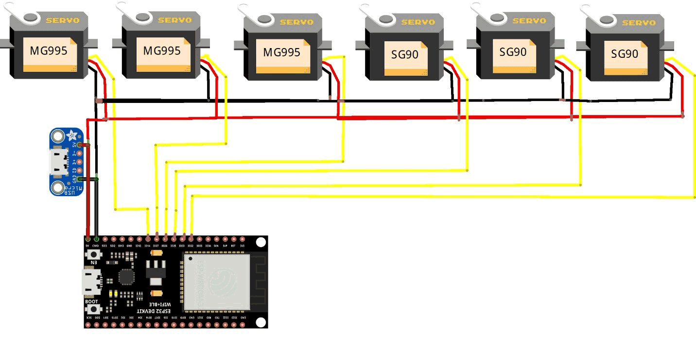
Each control Signal pin of the Servo is connected to the Digital PWM pins of the ESP32. We are using Six Servos of which three of them are MG995 high torque and rest three are SG90 servos. I have connected signal pins to 14,27,26,25,33,32 digital pins of the board. You can also use other pins, but make sure that it supports PWM (Pulse width Modulation) and that it is properly assigned inside the code.
Note: Do not power the Servos directly from ESP32, doing so will results in damaging the board.
Make All the connections to the perf board by using Male/Female headers for attaching separately Microcontroller board & jumper wires without direct soldering. Also, be careful about short-circuiting while soldering.
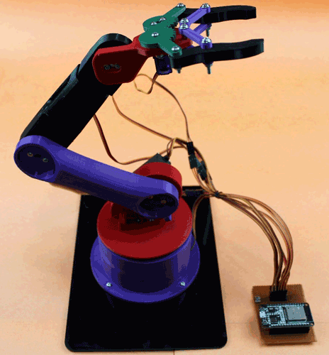
After all the setup and connections of the servos to the controller board, the final RoboArm is ready to proceed with the programming section.
Programming the ESP32 for Robotic Arm
The program uses the WiFi capabilities of the Esp to connect with a WIFI connection through which we can further able to control the RoboArm using our webpage. We will also learn about creating the webpage and controlling all the motions of the Arm.
To ensure successful program execution, we first include the necessary libraries: Servo.h and WiFi.h. The Servo.h library is utilized to control servo motors by providing the appropriate PWM signal based on the desired angle.
We create six different objects of the Servo class, each with a unique name, as we are using six distinct servos.
Furthermore, we define six additional variables to assign the control pins of the microcontroller. It is essential to verify the hardware connections before assigning PINs to avoid incorrect servo functionality.
The Wi-Fi credentials are defined using a pointer variable named "ssid" and “password”. These credentials are necessary for establishing a successful connection to a wireless network.
Following that, an instance of the WiFiServer object is created, named "server", with the HTTP port number 80 passed as an argument.
Additionally, the code declares variables to store the positions of sliders, which will be utilized for controlling the servo motors.