
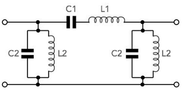
RF filters are a key part of RF design as the filters enable the required signals to be selected and unwanted ones removed.
- It is an electronic component that is used to allow or block selected signals or frequencies to eliminate noise or pass-through of unwanted signals.
- The RF filter is defined as passing radio frequencies within the desired band and blocking the undesired or unwanted radio frequencies in a wireless communication chain.
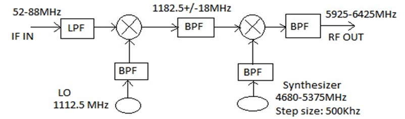
- These filters have various types based on the requirement. Such as in the RF up-conversion chain below, used to convert 70 MHz IF input to 6GHz RF output filters is employed as per need in the design.
- As shown below figure the input is 52-88 MHz low pass filter is used using discrete components.
- The low pass filter frequency is mixed with a local oscillator frequency of 1112.5 MHz and generates a new output signal 1182.5 MHz.
- After the first mixer BPF (band pass filter) new output signal is 1182.5 MHz with a bandwidth of 36MHz employed.
- Then the second stage of mixing, a 5925 to 6425 MHz microstrip-based parallel coupled band pass filter is incorporated.
- There are two types of RF filter.
- Low pass Filter
- High pass Filter
Low Pass Filter:
- It is the type of frequency domain filter that is used for smoothing the image. It attenuates the high-frequency components and preserves the low-frequency components.
High Pass Filter:
- It is the type of frequency domain filter that is used for sharpening the image. It attenuates the low-frequency components and preserves the high-frequency components.
Applications of RF & Microwave Filters
- RF filter is used in broadcast receivers to select desired channel frequency and reject all the other frequency channels.
- It is used in image frequency rejection in radio and TV receivers as well as satellite receivers.
- The RF filters are also used in multi-way loudspeakers.
- This filter is used for noise reduction.
- They are also used to stop LO leakage in RF transceiver designs.
Basic of RF Attenuators and Types
RF attenuators have a surprising number of uses: reducing high power signals for test equipment, level control; impedance matching, and several other RF circuit design areas.
- These attenuators reduce the amplitude level of an incoming signal.
- It is used to protect systems from receiving a signal with a power level that is too high to process.
- It is used to provide an accurate impedance match as most fixed attenuators offer a well-defined impedance, or attenuators may be used in a variety of areas where signal levels need to be controlled.
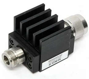
- This is required to reduce high levels of power and as a result, they may need to incorporate a heat sink to ensure that the power can be suitably dissipated.
- RF attenuators, as their name suggests, attenuate the signal by lowering its level. Fixed attenuators may be offered in a range of ranges, and the attenuation is often expressed in dB.
- This attenuation may be necessary to prevent a circuit stage from being exposed to an excessively strong signal.
- Additionally, as most fixed attenuators have well-defined impedances, attenuators can be used to accurately match impedance or in a variety of other applications where signal levels need to be controlled.
- These RF attenuators have a wide range of applications, and even though they may not always be immediately apparent, they are frequently used in RF circuit design applications and RF systems of various types.
Applications of RF Attenuators
- They are widely used in RF circuit design applications and RF systems of different types.
- It is used in volume control equipment in broadcasting stations.
- It is used for testing purposes in laboratories, to obtain smaller voltage signals.
- They are used to improve impedance matching in circuits.
- These are used to protect the circuits from damage caused by high voltage values.
- RF attenuators are used for the protective dissipation of power in measuring RF signals.
- Optical attenuators are applied in fiber optic communication to properly match transmitter and receiver levels.
Types of Attenuators
- There are two types of attenuator variable attenuator and fixed attenuator.
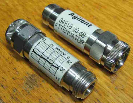
- Fixed Attenuators: Fixed attenuators are usually available in a surface mount package. They are passive attenuators that provide a fixed attenuation level. Most of these products are available in a series, which has several attenuation levels available.
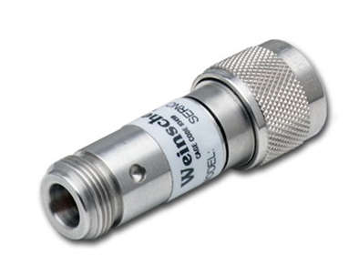
- Variable Attenuators: Variable attenuators provide an attenuation range i.e. they can be regulated to provide a particular attenuation level. Typically, the attenuation level can be modified by changing the voltage applied to an input control line.
Specification of RF Attenuators
- The frequency range over which it should work.
- Impedance value whether 50 Ohm or 75 Ohm.
- Attenuation value in fixed value or variable steps or continuously variable in the unit of dB.
- Type of connector for connectorized version such as SMA, N-type, BNC, TNC, and more.