
Circuit Diagram
The Complete circuit diagram for this PIC Microcontroller based Robotic Arm is shown below. The schematics was drawn using EasyEDA.

The circuit diagram is pretty simple; the complete project is powered by the 12V adapter. This 12V is then converted to +5V using two 7805 Voltage regulators. One is labeled as +5V and the other is labeled as +5V(2). The reason for having two regulators is that when the servo rotates it pulls in a lot of current which creates a voltage drop. This voltage drop forces the PIC to restart itself, hence we cannot operate both the PIC and the servo motors on the same +5V rail. So the one labeled as +5V is used to power the PIC Microcontroller, LCD and Potentiometers and a separate regulator output which is labeled as +5V(2) is used to power the servo motors.
The five output pins of the potentiometers which provide a variable voltage from 0V to 5V are connected to the analog pins An0 to AN4 of the PIC. Since we are planning to use timers to generate PWM the servo motors can be connected to any GPIO pin. I have selected pins form RD2 to RD6 for the servo motors, but it can be any GPIO of your choice.
Since the program involves a lot of debugging, a 16x2 LCD display is also interfaced to portB of the PIC. This will display the duty cycle of the servo motors that are being controlled. Apart from this I have also extended connections for all GPIO and analog pins, just in case if any sensors need to be interfaced in future. Finally I have also connected the programmer pin H1 to directly program the PIC with pickit3 using the ICSP programming option.
Generating PWM signals on GPIO pin for Servo Motor Control
Once the circuit is ready we have to figure out how to generate PWN signals on the GPIO pin of PIC to control the servo motor. We have already tired something similar using the Timer interrupt method and were successful. Here we are just going to build on top of it, so if you are new here, I would strongly recommend you to read this previous tutorial before proceeding further.
All hobby servo motors work with a frequency of 50Hz. Meaning one complete pulse cycle for a servo motor will be 1/50 (F=1/T) which is 20ms. Of this complete 20ms the control signal is only from 0 to 2ms while the rest of the signal is always off. The below figure shows how the ON time varies only from 0 to 2ms to rotate the motor from 0 degree to 180 degree of the total 20ms duration.
With this in mind we have to write the program in such a way that the PIC reads in 0 to1204 from the potentiometer and maps it to 0 to 100 which will be the duty cycle of the servo motor. Using this duty cycle we can calculate the ON time of the servo motor. Then we can initialize the timer interrupt to overflow at a regular interval such that it acts similar to the millis() function in Arduino. With that, we can toggle the status GPIO pin to be high for a desired duration and turn it off after 20ms (one complete cycle) and then repeat the same process. Now, that we have understood the logic let us get into the program.
Simulation of PIC Robotic Arm Code
It is always better to simulate the code before taking it to the real hardware. So I used Proteus to simulate my code and verified it to work correctly. The circuit used for simulation is shown below, We have used an oscilloscope to check if the PWM signals are being generated as required. Also we can verify if the LCD and Servo motors are rotating as expected.
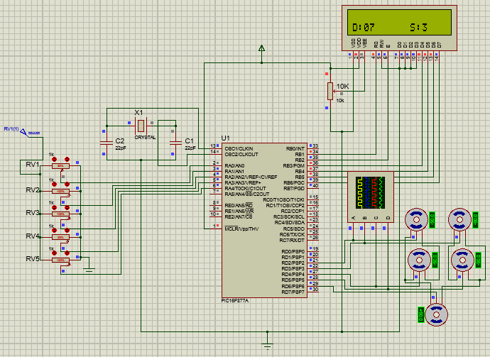
As you can see the LCD displays the duty cycle of motor D to be 07 based on the pot value which is the 3rd motor. Similar if another pot is moved the duty cycle of that pot and its motor number will be displayed on the LCD. The PWM signal shown on the oscilloscope is shown below.
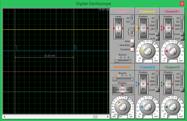
The total cycle period is measured to be 22.2ms using the cursor option on the oscilloscope, which is very close to the desired 20ms. Finally we are sure that the code works, so to continue with the circuit we can either solder it on a perf board or use a PCB. It will not work easily on breadboard because the POT always tends to give some problems due to poor connections.
Working of PIC Robotic Arm
After all the tiring work it is time for pay off. Solder all the components on the board and upload the program to the PIC controller. Complete Code is given below or can be downloaded from here. The programming connector provided on the board should help you upload the program directly using Pickit 3 without much hassle. Once the program is uploaded you should see the LCD displaying the servo that is currently being controlled. To learn more about programming the PIC Microcontroller, just follow the previous tutorial.
