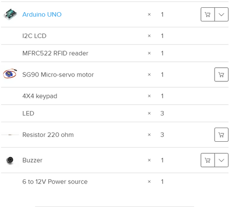
Things used in this project
Hardware components

In this post, you are going to learn about how to build an RFID and Keypad based door lock using Arduino. To open the door, the user will have to first scan the right tag and then he will have to enter the correct password. On scanning the wrong tag or on entering the wrong password, the system will deny access.
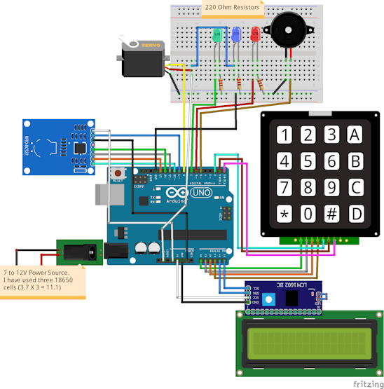
Circuit Diagram and Explanation
The RFID reader communicates with the Arduino through the SPI protocol and different Arduino boards have different SPI pins.
To test if the RFID reader is working properly or not, upload the “dumpinfo” from the examples in the Arduino and see if it is showing the information of the tags on the serial monitor or not. If you are new to RFID, then follow this tutorial | RFID basics and RFID module interfacing with Arduino
The I2C LCD communicates with the Arduino through the I2C protocol. Different Arduino boards have different I2C pins. The I2C pins on Arduino Uno and Arduino Nano are A4, A5.
Next connect the keypad with Arduino. The 4X4 keypad has 8 connections but we don’t require the last column of keypad. We only require numbers for the password. So we won’t use the last pin of keypad which is for fourth column. You can also use 4X3 keypad instead of 4X4 keypad.
Next connect the Led's, servo and buzzer with the Arduino as shown in the below diagram.
In the end, connect the power source to the Arduino. I have used three 18650 cells. We can give 6 to 12V to the Arduino through the barrel jack.

Code
The initial password is ‘1234’.
Change the tag’s UID in the below line of code with your tag’s UID.
String tagUID = “29 B9 ED 23”;
