
The Relay Module
What’s the relay module to begin with? The relay module is a type of device that helps you control an electrical circuit by opening or closing a switch.
This is made possible by the electromagnet inside the relay. When the switch is turned on, the electromagnet becomes activated, which in turn either opens or closes the circuit, depending on its intended purpose
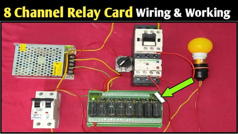
You can use a relay control module in many different situations, such as providing a remote control for lights, electric motors, and other appliances. It can also be used in safety and security systems to sound an alarm or to activate or deactivate a device.
Relay Module Circuit
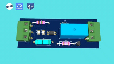
The relay module circuit includes the printed circuit board (PCB) where the relay and several other parts are soldered. The relay module PCB is designed to provide a space for the components and to connect them electrically.
The circuit ensures current flows from the input to the output in the right order and with the right magnitude.
The relay module circuit diagram at the beginning of this post shows the connection between the relay, control board, and other electronic components. The input of the circuit is usually connected to the microcontroller device, while the output is connected to the load.
Relay Module Components
The relay module is composed of the relay itself, control board, and a few electronic components, as already mentioned. More about these relay module parts below, including their function in the circuit.
Module Relay
The module relay itself is an electromagnet switching device. It consists of a coil and armature mechanism, which is activated when current flows through it, and a switch that opens or closes the circuit.
When the electromagnet is activated, the switch either opens or closes the circuit, depending on its intended purpose. The relay can be used to turn on or off a light bulb, motor, or any other device.
Relay Module Board
The control board is the heart of the relay module circuit and components. It’s where the relay unit input and output pins are held. The relay module control board also contains the components that make the device work. These include transistors, diodes, resistors, and capacitors.
- The relay module transistor is used to control and amplify the current flowing from the microcontroller.
- The relay module LED, on the other hand, indicates whether the switch is open or closed.
- A flyback or freewheeling diode is also used. It protects against voltage spikes that can occur when the current flowing through the coil is interrupted.
- Resistors are used to limit the current flowing through specific parts of the relay module circuit.
Relay Module Optoisolator
Some relay modules come equipped with optocouplers to further isolate the microcontroller from the high voltage circuit. There are many types of optocouplers, but they all work in a similar way.
A relay module with optocoupler isolation basically has an LED and a phototransistor placed side-by-side inside a package. The LED emits light, which is used to activate the photodiode.
The photodiode is then used to switch the current on or off. This way, the opto-isolated relay module can control the load without directly exposing the microcontroller to the high-voltage circuit.

Relay Module Connections
Relay module connections here are used to refer to the input signal and high-power output or load connections. The input links to the microcontroller device, while the output connection is made to the load. More about the relay module pins below.
- The relay module input side normally has three pins: VCC, GND, and IN. The VCC is the positive voltage supply, while GND is the negative terminal or ground. The IN pin is the input signal pin, which is used to activate the relay.
- The output side of the relay module has two pins or screw terminals: NO (normally open) and NC (normally closed). The NO terminal is used to connect the load when the relay is activated. The NC terminal is used to connect the load when the relay is deactivated.
The default relay module connection on the output/load side will depend on the required configuration. If a device must remain off until the relay is activated, the NO configuration is used and vice versa.
How to Wire a Relay Module
The relay module wiring involves connecting the input, output, and power connections. As you can see in the above circuit diagram, the input and output connections are made to the microcontroller device and load. The following descriptions show how to wire a relay module:
- VCC pin of the microcontroller -> VCC pin of the relay module
- GND pin of the microcontroller -> GND pin of the relay module
- IN pin of the microcontroller -> IN pin of the relay module
- NO pin of the relay module -> Load
- NC pin of the relay module -> Open circuit or not connected
When wiring a relay module, make sure that the power supply voltage (VCC) and ground (GND) are connected properly. The IN pin of the microcontroller is used to control the relay.
When a HIGH signal is applied to this pin, the relay is activated, and the load is turned on. When the IN signal is LOW, the relay is deactivated, and the load is turned off.