
Reducing undetected PCB collisions...
When placing parts on a PCB layout, we are most often placing components that have no interface to the outside world. Resistors, capacitors, and low power ICs are great examples. We download a STEP model for the component, incorporate it into the footprint, and place the part onto the PCB.
This approach is not favorable if your component interfaces to the outside world, because the manufacturer's STEP model will rarely include any objects external to the component itself. I/O headers, high power ICs which require a heatsink, and LEDs needing light pipes are great examples of such parts with interfaces.
If your component interfaces to an external part, using the manufacturer's STEP model can result in undetected collisions when you run the DRC. Unfortunately, these collisions are most often uncovered after PCB fabrication, and during board assembly.
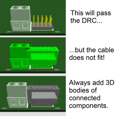
In the example below, a terminal block is placed adjacent to a 10-pin I/O header. Notice that without a connected ribbon cable (top), a collision is not detected and the DRC passes. But after we add a cable, we learn that the terminal block is placed too close to the I/O header (middle).
To resolve the issue, incorporate 3D bodies of interfacing components to your footprints. Your DRC will detect the collisions, and you will reduce the problems on your PCB spin.