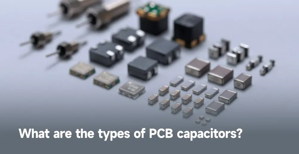
What is a PCB capacitor?
A PCB capacitor is a crucial component in an electronic circuit that stores and releases electrical energy. These capacitors are specifically designed to be used on printed circuit boards and are generally small in size, making them ideal for use in space-limited electronic designs. PCB capacitors can be surface-mounted on the PCB, allowing for efficient use of board space. They come in a variety of capacitance values, voltage ratings, and types, enabling designers to choose the right capacitor for their specific electronic design requirements.
What are the types of PCB capacitors?

There are several types of PCB capacitors available in the market, each with unique features and specifications. Some of the commonly used PCB capacitors types are:
● Ceramic capacitors: These are the most commonly used type of PCB capacitors. They are small, inexpensive, and offer stable performance over a wide range of frequencies. Ceramic capacitors are available in a range of capacitance values and voltage ratings.
● Electrolytic capacitors: These are larger in size compared to ceramic capacitors and can store a larger amount of energy. Electrolytic capacitors are polarized, which means they have a positive and a negative terminal. They are commonly used in power supply circuits.
● Tantalum capacitors: These capacitors offer high stability and accuracy, making them a popular choice in precision circuits. Tantalum capacitors are also polarized and can handle higher voltages compared to ceramic capacitors.
● Film capacitors: Film capacitors use a thin plastic film as the dielectric material, providing high stability and accuracy. They’re ideal for use in audio circuits and high-frequency applications
● Super capacitors: These are also known as ultracapacitors, and they can store a larger amount of energy compared to other capacitor types. Super capacitors are commonly used in backup power applications.
Why is a PCB capacitor important for PCB?
PCB capacitors play a crucial role in stabilizing the voltage and filtering out noise in electronic circuits. They store and release electrical energy as required, which helps in maintaining a stable power supply to the electronic components. PCB capacitors are also used in power supply circuits to smooth out voltage fluctuations and provide a stable DC voltage. Without PCB capacitors, electronic circuits would be unstable and prone to failures.
How do PCB capacitors work?

PCB capacitors are the crucial component in modern electronic devices, providing a means of storing and releasing electrical energy to power circuits. These capacitors utilize the principle of electric fields to store energy between two conductive plates separated by a dielectric material. When a voltage is applied, energy is stored, and when it’s removed, the capacitor discharges, providing the required electrical energy to the circuit.
Understanding how PCB capacitors work is crucial for anyone working with electronic devices, as it allows for the selection of the correct capacitance and voltage ratings for the design’s specific requirements.
How to measure the PCB capacitance?
Measuring the capacitance of PCB capacitors is crucial to ensure its proper functionality in an electronic circuit. With several methods available, it can be challenging to determine the most accurate and efficient one. Here are some ways to measure the capacitance of PCB capacitors:
● Utilizing a capacitance meter: A capacitance meter is the most reliable and commonly used method to measure the capacitance of a capacitor. The capacitance meter can measure the capacitance of the capacitor accurately and quickly.
● Employing an oscilloscope: An oscilloscope can also measure the charging and discharging of a capacitor and calculate its capacitance. This method requires technical expertise and may take longer than using a capacitance meter.
● Using a multimeter: A multimeter can measure the capacitance of PCB capacitors, but it may not be as accurate as a dedicated capacitance meter. This method is best suited for quick and rough measurements.
By selecting the appropriate method, you can ensure the accuracy of your measurements and optimize the performance of your electronic circuits.
What is PCB parasitic capacitance?

PCB parasitic capacitance refers to the capacitance that exists between different components and traces on the PCB. It is an unwanted capacitance that can affect the performance of the electronic circuit. Parasitic capacitance can cause noise, interference, and signal distortion in the circuit. PCB designers need to consider the parasitic capacitance and try to minimize its effect on the circuit.
What factors should be considered when choosing a PCB capacitor?
When selecting a PCB capacitor, several factors need to be considered, including:
1. Capacitance value: The required capacitance value depends on the application and the circuit’s requirements. The capacitor’s capacitance value should be within the required range to ensure proper functioning.
2. Voltage rating: Ensure the capacitor’s voltage rating is higher than the maximum circuit voltage to prevent damage.
3. Type of capacitor: The type of capacitor depends on the application and the circuit’s requirements. Ceramic capacitors are the most commonly used type of PCB capacitors, but other types may be more suitable for specific applications.
4. Size and shape: The size and shape of the capacitor should be appropriate for the available space on the PCB.
5. Operating temperature: The capacitor’s operating temperature should be within the required range to ensure proper functioning.
How to place your PCB bypass capacitor?
Bypass capacitors are used to filter out noise and stabilize the voltage in electronic circuits. They are usually placed as close as possible to the power and ground pins of the electronic component they are connected to. When placing the bypass capacitor on the PCB, the following guidelines should be followed:
● The capacitor should be placed as close as possible to the power and ground pins of the electronic component.
● The capacitor’s leads should be kept as short as possible to reduce the parasitic inductance and resistance.
● For optimal performance of the capacitor, it is recommended to mount it as close to the ground plane as feasible to decrease the undesirable capacitance that may occur between the power and ground planes.
