
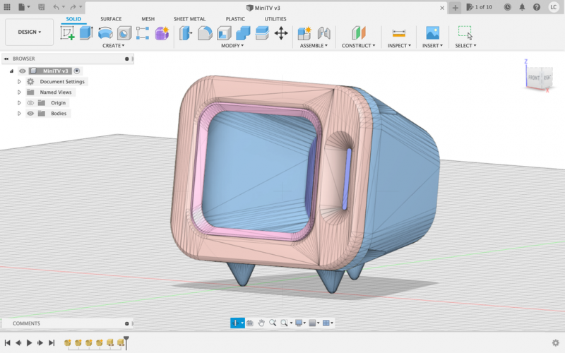
- CRT attributes
- Standard of analog TV format
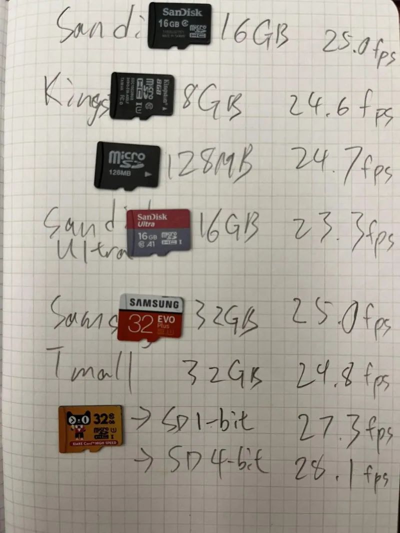
Previous posts have tested the speed of SD cards running on the ESP32, and the ESP32 can only read SD cards at about 2 megabits per second. MicroSD is rated in four levels to meet the requirements. Faster cards do not help improve performance.
Adjust the audio gain level set (optional)
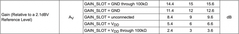
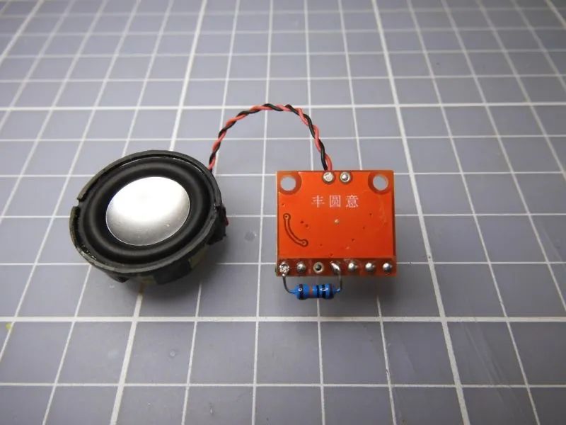
The 24 mm full frequency audio speaker is rated at 2-4W, and the MAX98357 audio board can support output up to 3.2W, so the speaker is able to output the maximum gain setting of the audio board. But we have to set the volume of the TV reasonably, and I think a 3dB gain level would be better.
Power distributor
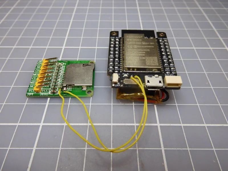
The TTGO T7 development board can be powered by USB, or it can be connected to a lithium battery as an unplugged power supply, so other components can get power from the development board.
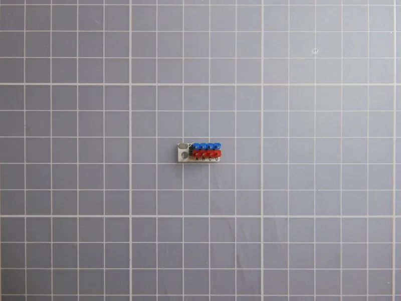
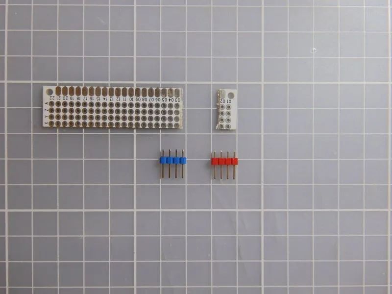
But the development board only has a 3v3 row of pins, so it needs a small pin separator to make power pins.
Battery powered (optional)
The TTGO T7 development board has a built-in lithium battery holder to charge Lipo. So you can add a Lipo to the TV that can be installed under the development board. In theory, a 600mAh Lipo can be used for about 1-2 hours. The video above shows that the battery can play for 44 minutes without any problems.
MicroSD card insertion switch (optional)
Adding a MicroSD card insert switch requires some welding skills.
Most microSD card slot splints cannot be disconnected from the insertion detection switch, so you will need to disconnect manually. Then connect it to the TTGO T7 power switch. In this way, once the micro SD card is removed, the TV will automatically turn on or off when you remove the card.
In the last century, when we put a rented disc into a video recorder/player (VCR), we could watch a movie on the sofa. So I designed this optional Micro SD card insertion switch.
Connection method
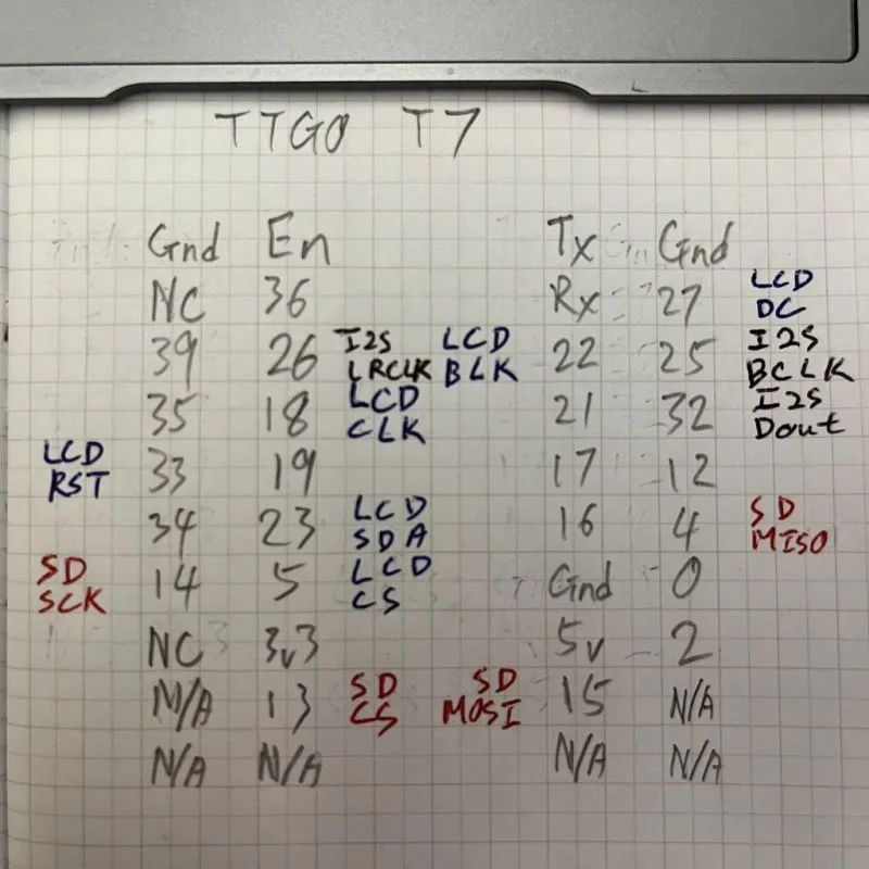

If you want to try using SD_MMC, SD card MISO needs to be connected to GPIO2, but remember to disconnect GPIO2 when uploading the program.
If the audio output is too noisy, it may be that the 3v3 power supply is not enough for the MAX98357, you can consider changing the MAX98357 power supply to 5v.