
Translating LVDS to LVPECL, CML, or Other Differential Standard
The goal in any translation between differential logic families is impedance matching throughout the signal bandwidth. This can be difficult if you need to compensate for dispersion, but dispersion tends to flatten out at high signal bandwidths. The image below shows a general high-speed differential interconnect between two differential components.
The driver has some output impedance (RS) for each trace in the pair. In some cases, you’ll need to add series resistors at the driver end to match the driver’s output to the traces’ characteristic impedance. The typical characteristic impedance of 50 Ohms is shown in the image, and the receiver’s parallel termination resistance (RD) is shown at the far end of the pair. RP and RN are pull-up and pull-down resistors in Thevenin configuration for each trace; these are used to convert active-HIGH and active-LOW signals as required (receiver end only) to step-up/step-down the differential voltage is seen at the receiver. DC blocking can be provided by series capacitors, which becomes important when interfacing to a CML receiver.
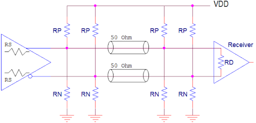
General network for converting between differential signals.
Before looking at some specific pairs of differential signaling translations, there is something important to realize about the above graphic; you can’t convert an upstream signal to a higher signal level unless there is a downstream power source that supplies higher voltage. You may need to add step-up or step-down resistors at the driver and receiver ends to make the signal levels compatible.
The image below shows a few examples involving LVDS to LVPECL translations. Another translation involving DC blocking capacitors is shown for LVPECL to CML. Note that, for the LVDS/LVPECL transitions, the termination resistor may be integrated into the driver’s input; be sure to check your component datasheets to see if a terminating resistor is required on the input. For the LVPECL/CML translation, the series capacitors should be sized like a high pass filter, although pay attention to the input capacitance on the receiver.

What About Differential to Single-ended Translations?
If you need to receive a differential signal as a single-ended signal at a receiver or transmit a single-ended output as a differential signal, you have a few options. For receiving differential signals and interpreting as single-ended, FPGAs have settings that will translate the input into the required level to be read as a single-ended signal. If you aren’t working with an FPGA and you simply need to transmit over some physical layer, you’re better off using an amplifier with unity gain and high bandwidth. In other words, find an amplifier IC that has a high gain-bandwidth product, and set the gain to the value that will produce the single-ended signal level you need, just as you would with an op-amp circuit.
If you’re translating between specific differential and single-ended logic families (e.g., LVDS to LVTTL/LVCMOS), you can use a translator IC. The MC100EPT21 (ON Semiconductor) is one example of such a component. If you need to go the other direction, you can use a single-ended to the differential translator that supports your desired logic family. The 85320I (Renesas) is one example of a single-ended to the differential translator.
This type of single-ended to differential conversion is useful if you want to transmit a single-ended signal over a physical connection as a differential signal. This is one option for board-to-board cable connections in noisy environments where you would normally need to route multiple ground lines across a cable. Increasing the wire count and transmitting differential signals may take up some extra space on the board for a pin header or pin-and-socket connector. Still, you’ll have a high common-mode rejection ratio at the receiver.
If I needed to do this type of connection between boards with a single-ended output, I would look for a connector with consistently rated impedance up to the band edge for my signal. Some connectors designed for differential signaling are rated in terms of maximum data transfer rate, not as a frequency. Board-to-board edge connectors and pin-in-socket with standard form factor and high data rates (e.g., PCIe) are available on the market. No matter which route you choose to take in your layout, you’ll need the right schematic design tools and PCB CAD tools to make it possible.