Virtual Ground and Virtual Short in Op – Amp Circuit Designs
What is Virtual Ground and Virtual Short?
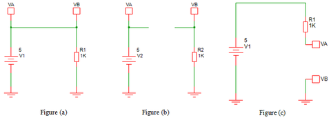
Before getting into the details, let us take a look at the figures given below. In Figure (a), the voltage at VA = VB, this is because there is a short circuit between VA and VB point. In figure (b), there is no connection (short circuit) between VA and VB. But still the voltage at VB = VA without connection with any other source means there should be a virtual connection in between VA and VB or due to some other virtual effect the VB is equal to VA. This is an effect commonly knows as “Virtual Short Circuit”.

Likewise, in Figure (c), even if the VA is connected with a 5V source but due to some effects if the VA= VB = 0V (Gnd_Potential) means this effect will be called as “Virtual Ground”.
The above mentioned details may seem like magic or unrealistic. But, the basic Op-Amp operations follow the above two concepts, and understanding the reason behind this will help to understand full Op-Amp physics.
Basic Op-Amp working Rules:
The Basic Op-Amp working mechanism mainly follows below given 2 important rules
- Always the Voltage at Non-Inverting Input and Inverting input of the Op-Amp should be Equal. The internal Op-Amp design and output feedback resistors always tend to make them equal in order to maintain the stable Operation Op-Amp.
- As per the Op-Amp characteristics, the Op-Amp has higher input impedance and lower output impedance. So, for ideal Op-Amp operation, the current flow through Op-Amp input terminals are assumed as “Zero”.
Virtual Short in Op-Amp
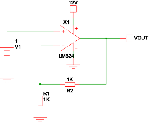
The below circuit is the famous non-inverting Op-Amp topology which has 1V input and having the gain resistance of R1 = R2 = 1KΩ. It has some defined equations in order to find the relation between Input and Output Voltage relation. Instead of using those defined formulas, we can apply the Basic Op-Amp rules in order to find the output voltage.

As per Rule - 1, the Inverting Input (-) voltage should be equal to the Non-Inverting (+) input voltage, for the given circuit, the V_Non_Inverting = 1V. Like Non-Inverting (+) pin the Inverting pin (-) not connected to any dedicated voltage source and only the Op-Amp VOUT can make the Inverting (-) terminal voltage to 1V.
So, once the Op-amp gets “Powered On” the internal parameters of Op-Amp are worked to bring Inverting Input voltage equal to 1V and as per rule to there is no current flow through the Inverting pin. Due to that R1 & R2 becomes voltage divider with VOUT as a Source voltage and Voltage divider output should be equal to Non-Inverting Input Voltage.
The output voltage is varied to either higher or lower voltage levels from its previous state in order to bring the V(+) = V(-). Here, due to R1=R2 and both make voltage divider combination and the VOUT = 2V makes (V+) = V(-).
Based on the below Non-Inverting Op-Amp gain equation:

So, for Non-Inverting Op-Amps the Inverting Pin Voltage is equal to Non–Inverting voltage without direct short circuit between both the terminal and the Equaling Voltage at both the terminals happens by Virtual Concept and this effect is called as “Virtual Short in Op-Amp”.
Virtual Ground Concept in Op Amp
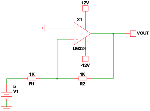
By applying Rule 1 and 2 in the below Inverting Op-Amp configuration, the Voltage at Inverting Pin should be Zero. But, the Inverting pin (-) is connected to a 5V source via R1. As per Rule 2, there is no current flows through Inverting (-) Input and all currents are flows through R1 and R2. In order to make the V(-) = 0, the VOUT has to supply compensating voltage.
In the given circuit, the Positive 5V is supplied to Inverting terminal via a 1K resistor, and to make the Inverting terminal voltage = 0 the VOUT should be -5V (due to R2 = 1K). If the R2 Value is modified, then the VOUT also should be modified by the Op-Amp internal structure to make V(In-) = 0.
For Inverting Op-Amp Configuration => V1/R1 = -VOUT/R2

In this Inverting Input Configuration, the Inverting input is always mentioned at the “Ground Potential” (due to Non-Inverting Input Ground Potential) without direct connection with the ground because of Op-Amp internal functions. Even the Inverting Input is supplied with a 5V source, the Inverting Terminal Voltage is equal to “Gnd” and this is the reason behind of calling it as “Virtual Ground” or Virtual Earth.
Importance of Virtual Ground and Virtual Short in Op-Amp
The Virtual Ground and Virtual Short are the two important parameters that are used to examine any Op-Amp circuit. Most of the Op-Amp circuit derivations and transfer functions formulated based on these two concepts and make the circuit analysis simpler without considering the input parameters of the Op-Amp.
The Virtual Ground and Virtual Short Concept are only applicable for “Closed Loop” Op-Amp circuits. In Open Loop or the Op-Amp used as comparators, there is no feedback mechanism to control the matching between Inverting and Non-Inverting Input Voltage. So, the Op-Amp always operates in Saturation mode and Virtual Ground, Virtual Short Concepts doesn’t work. In these types of Conditions, the designer should look into the “Differential Input” Voltage limits in order to avoid the Op-Amp malfunctions.
In some of the Closed-loop conditions also the Virtual Ground and Virtual Short concepts will get void when the output matching limit exceeds the Op-Amp Vcc and Vee supply ranges.
Examples of Virtual Ground and Virtual Short Void Conditions
 |
Here, the Vee = Gnd and Negative voltage can’t be delivered by the Op-Amp output due to the unavailability of Negative rail. So, the Virtual Ground Condition is Void. |
 |
To bring the Virtual Short, the VOUT should be equal to 50V and the Vcc = 12V and the Op-Amp saturated to 12V level and Virtual Short condition is Void. |
 |
In this circuit, in order to make V(+) = V(-), the Feedback Element is not available, and it is operated as Open Loop Comparator. So, the Virtual Short Concept is Void. |
