HOW SERVOS WORK
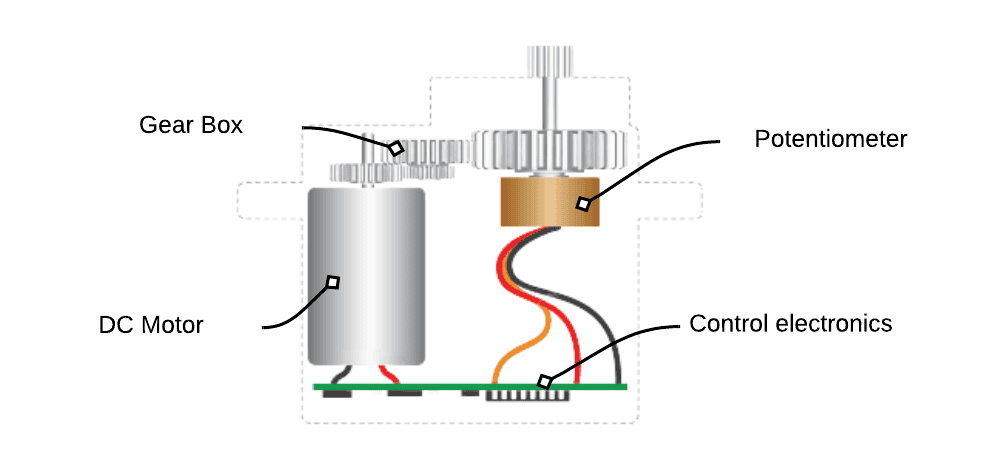
To understand how servos work, take a look at the internal structure of a servo:

The diagram above shows the various components of a servo. Servos have a DC motor, a gearbox, control electronics, and a potentiometer.
Unlike DC motors that spin continuously in one direction, servos allow precise control of the angular position of the motor shaft between 0° and 180°. To achieve this, we make use of a feedback loop, as shown in the diagram below.

The user enters the desired position of the servo shaft by sending a pulse width modulation signal to the servo. The target position signal is then interpreted by the motor controller, which will turn the shaft. Next, the position of the shaft is measured by the potentiometer, and the result is fed back to the motor controller. The difference between the original input signal and the feedback signal is used to set the motor current in the next cycle of the feedback loop. As the difference between the two signals gets smaller, the position of the sensor shaft gets closer to the desired position
HOW TO POWER SERVOS
The SG-90 micro servo draws roughly 650mA of current, which is more than the Raspberry Pi’s GPIO pins can provide. The best solution is to use an external power supply to provide the current to drive the servos. A good technique is to power the servos with a 9V battery. The 9V battery can provide enough current for at least four servos.
HOW TO SET THE POSITION OF A SERVO
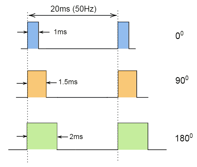
The position of a servo motor is set by adjusting the length of the high pulse (the pulse width) in a pulse width modulation signal. The servo typically accepts a 50Hz pulse width modulation signal frequency. As we can see in the diagram below, a 1ms pulse width gives a servo angle of 0°, 1.5ms pulse width moves the servo to 90° and finally, a 2ms pulse width will set the servo at 180° .

HOW TO CONNECT A SERVO TO THE RASPBERRY PI
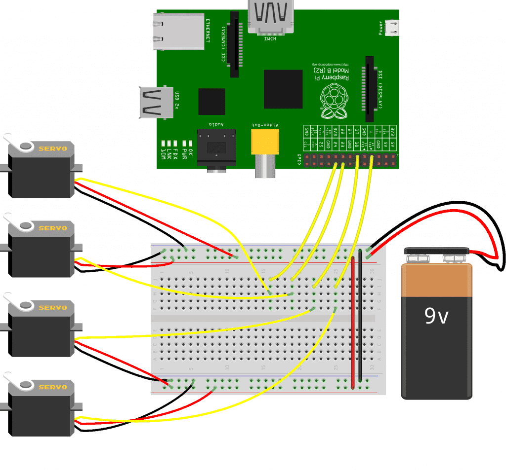
Connecting servos to the Raspberry Pi is easy. In this project we are going to connect four SG-90 micro servos to the Raspberry Pi and control the position of each servo with a graphical user interface.
These are the parts we will need:
- Raspberry Pi
- Four SG-90 micro servos
- Breadboard
- 9V battery
- 9V battery connector
- Jumper wires
Once you have all of the parts, connect the servos to the Raspberry Pi following this wiring diagram:

SG-90 SERVO PINS
The SG-90 servo motor has three wires. Each wire has a particular function, described in the table below:
| Red wire | 5V power input pin |
| Brown wire | Ground |
| Orange wire | Pulse width modulation signal input pin |
HOW TO PROGRAM THE SERVO WITH PYTHON
In the Python code below, we will use the AngularServo class from the gpiozero library to generate the pulse width modulation signals that control the servos.
