
9-axis sensors combine a magnetometer, accelerometer, and a gyroscope into a single sensor. The small size and low weight of these sensors make them perfect for building aircraft, drone, and robot navigation systems.
OVERVIEW OF THE MPU-9250 9-AXIS SENSOR
The MPU-9250 has three different sensors – a magnetometer, an accelerometer, and a gyroscope. Each sensor outputs data from the X, Y, and Z axes. That makes 9 axes in total, so the MPU-9250 is a 9-axis, or 9 degree of freedom sensor. Degrees of freedom are the total number of axes that can be measured by a sensor.
Here’s a pin diagram of the MPU-9250:
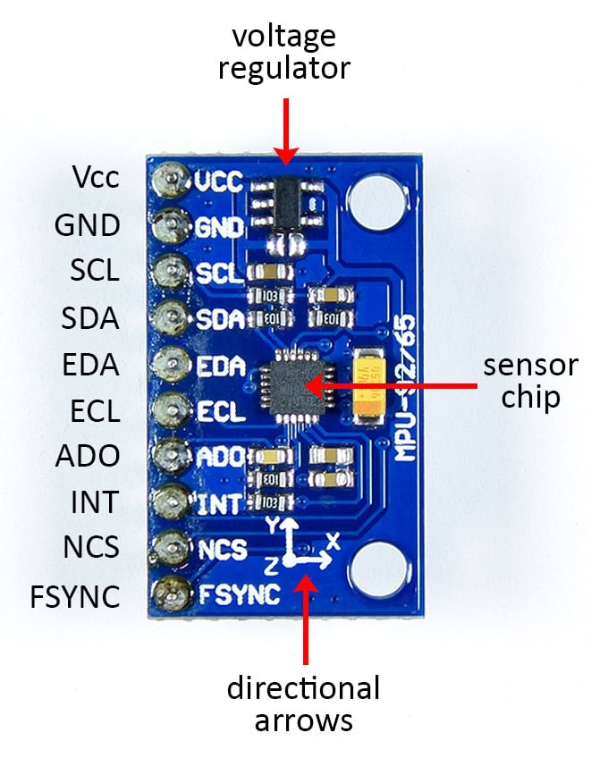
The MPU-9250 has ten pins:
- VCC: Power input. If the MPU-9250 PCB has a voltage regulator on it, it can be connected to either 3.3 or 5 volts. If no voltage regulator is present, the maximum voltage is 3.3 volts.
- GND: Connects to ground on the Arduino.
- SCL: For I2C communication. Doubles as the SCLK pin for SPI communication.
- SDA: For I2C communication. Doubles as the SDI pin for SPI communication.
- EDA: I2C master serial data pin. The MPU-9250 can be setup as an I2C master device to receive and output data from another sensor. This pin would connect to the SDA pin of the other sensor.
- ECL: I2C master serial clock pin. Would connect to the SCL pin of the other sensor.
- ADO: Used to change the I2C address of the sensor. When it’s low the I2C address is 0x68. When it’s high the address is 0x69. Doubles as the SDO pin for SPI communication.
- INT: Hardware interrupt pin. Can trigger a hardware interrupt from any of the sensor’s 9 axes.
- NCS: The CS pin for SPI communication.
- FSYNC: Frame synchronization digital input pin. Used to pass the hardware interrupt from an external sensor to the Arduino.
On top of the MPU-9250 PCB there should be some directional arrows that indicate the direction of the accelerometer and gyroscope axes in relation to the PCB board.
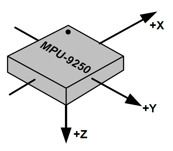
The magnetometer’s axes are aligned differently. It might be hard to see but there is a small dot on the upper left hand corner of the sensor chip. The magnetometer axes are oriented like this in relation to that dot:
HOW TO CONNECT THE MPU-9250 TO THE ARDUINO
The MPU-9250 can communicate with the Arduino over SPI or I2C communication. In this project we will use I2C.
Here are the parts you’ll need to build the project:
- Arduino Uno
- Jumper wires
- MPU-9250 9-axis sensor
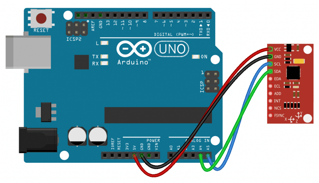
Follow the wiring diagram below to connect the MPU-9250 to the Arduino:
HOW TO PROGRAM THE MPU-9250 ON THE ARDUINO
The sketch below will print out the reading from each axis to the serial monitor. We will use a library called the MPU9250 library to program the sensor. You can download it from this link. Once the library is installed, upload this code to the Arduino:
#include "MPU9250.h" MPU9250 sensor(Wire, 0x68); void setup() { Serial.begin(9600); sensor.begin(); } void loop() { sensor.readSensor(); Serial.print("Accelerometer X: "); Serial.println(sensor.getAccelX_mss(), 2); Serial.print("Accelerometer Y: "); Serial.println(sensor.getAccelY_mss(), 2); Serial.print("Accelerometer Z: "); Serial.println(sensor.getAccelZ_mss(), 2); Serial.print("Gyroscope X: "); Serial.println(sensor.getGyroX_rads(), 2); Serial.print("Gyroscope Y: "); Serial.println(sensor.getGyroY_rads(), 2); Serial.print("Gyroscope Z: "); Serial.println(sensor.getGyroZ_rads(), 2); Serial.print("Magnetometer X: "); Serial.println(sensor.getMagX_uT(), 2); Serial.print("Magnetometer Y: "); Serial.println(sensor.getMagY_uT(), 2); Serial.print("Magnetometer Z: "); Serial.println(sensor.getMagZ_uT(), 2); Serial.print("Temperature: "); Serial.println(sensor.getTemperature_C(), 2); Serial.println("------------------------------------"); delay(500); }
EXPLANATION OF THE CODE
The first thing we do is include the MPU9250 library with #include "MPU9250.h". On the next line, we declare a sensor object from the MPU9250 class. We need to pass the communication protocol we’re using and the I2C address of the sensor to the sensor object. For I2C communication, use Wire as the first parameter. The second parameter is the I2C address. We left the ADO pin unconnected (low) so the I2C address is 0x68. If it was connected it to 5 volts, the I2C address would be 0x69.
To connect the sensor with SPI communication, use SPI for the first parameter and the Arduino pin connected the sensor’s CS pin as the second parameter.