
From the growing Internet of Things to the arrival of artificial intelligence, field-programmable gate arrays are steadily making their way into the future of electronics. Field-programmable gate array development is getting increasingly popular across various sectors and applications due to its versatility and constantly declining cost. However, as gadgets grow smaller and more linked, some may be difficult to use, making development impractical. On the other hand, field-programmable gate arrays are frequently helpful in developing devices, so using a link to control the device from a distance might be advantageous.
FPGAs are ICs programmed to carry out a predetermined set of tasks. Because they are programmable, we can modify FPGAs to suit the unique requirements of various applications. On the other hand, Arduino is a microcontroller board created for quick and interactive electronics prototyping. Its open-source infrastructure accommodates a variety of initiatives.
FPGAs
A digital circuit known as an FPGA can carry out any logical operation. PLBs, or programmable logic blocks, are the building blocks of FPGAs and we can combine them to form any digital circuit. The PLB can produce a variety of logical functions, including AND, OR, XOR, and NOT gates. Furthermore, the PLBs can be suitable for maths operations and other tasks like memory storage.
The advantages of FPGAs over conventional digital circuits are numerous. Secondly, FPGAs are flexible and adaptable to various applications because we can reprogram the. Second, because FPGAs can carry out many tasks, they can take the role of various digital circuits. Third, complicated digital circuits that are not feasible with conventional digital circuits can consist of FPGAs.
Arduino
A microcontroller board called Arduino is ideal for quick and interactive electronics prototyping. Arduino software programs the microprocessor at the heart of Arduino boards. The libraries and tools included with the Arduino software make it simple to write and upload code to the microcontroller. In addition, the input and output pins of Arduino boards can connect to sensors, actuators, and other electronic devices.
Anyone without an electronics background can easily develop their projects with Arduino hardware and software. Moreover, because of their low cost and simplicity of use, Arduino boards are also well-liked among students and hobbyists.
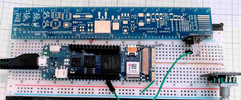
Connecting an FPGA to an Arduino Board
Connecting an FPGA to an Arduino Board

Connecting the two parts is the first step in using an FPGA with an Arduino. The connection technique will vary depending on the specific FPGA and Arduino boards utilized. There are typically two ways to link an FPGA to an Arduino:
GPIO Pins: Using the General Purpose Input/Output (GPIO) pins on the Arduino board is the simplest method for connecting an FPGA to an Arduino. Several GPIO pins on most Arduino boards can interface with external electronics. First, determine the precise pins on both the Arduino and the FPGA that will be helpful for communication if you want to link an FPGA to an Arduino utilizing GPIO pins. Once you’ve located these pins, you can link them with pins or a unique PCB.
Shields: Using a shield is another way to link an FPGA to an Arduino. The capability of the Arduino board can increase by attaching Arduino shields, which are pre-built modules. A variety of FPGA shields are available for use in securing an FPGA to an Arduino. The ports on these shields often enable direct connection of the FPGA to the Arduino board.
Steps of programming Arduino FPGA
The Arduino FPGA is a versatile platform for designing and programmatically manipulating unique hardware circuits. You may create intricate digital systems with an FPGA that carry out particular operations, such as data processing, signal filtering, and control logic.
By utilizing a hardware description language (HDL) to create a hardware design, synthesizing the design into a bitstream, and uploading the bitstream to the FPGA chip, you can program an Arduino FPGA. Below is a thorough breakdown of each action.
Step 1: Install the Necessary Software and Hardware
Setting up your development environment is necessary before you can begin writing code for an Arduino FPGA. This entails connecting the Arduino FPGA board to your computer and installing the required software programs, such as an HDL compiler, synthesis tool, and FPGA programmer.
The Xilinx Vivado development suite, used for FPGA design and synthesis, is included in the thorough instructions on setting up your environment and installing the software available on the Arduino website. The next step can be after you have connected your Arduino FPGA board and installed the software.
Install the Arduino IDE after downloading it: You will develop and upload your code to the FPGA board using the Arduino Integrated Development Environment. You can download the most recent version of the Arduino IDE at the official Arduino website.
After installing the Arduino IDE, you must install the FPGA board support package. This package contains the files and libraries required for programming the FPGA board. By selecting “Board” from the Arduino IDE’s “Tools” menu, followed by “Boards Manager,” you can install the board support package. Find the FPGA board you’re using in the Boards Manager, then select “Install.”
Connecting Your PC to the FPGA Board: Use a USB cord to link the FPGA board to your PC. Your computer ought to recognize the board right away.
Step 2: Create a Hardware Design
The following stage is to develop an FPGA hardware design using an HDL, such as Verilog or VHDL. To build and simulate complicated digital systems using software tools, HDL describes the behavior and topology of digital circuits textually.
A text editor or an integrated development environment (IDE) that supports HDLs, such as Xilinx Vivado or Quartus II, can generate a hardware design. The circuit’s inputs, outputs, and functionality, as well as the connections and logic gates that carry it out, are defined throughout the design process.
After creating your hardware design, save it as a Verilog or VHDL file for the next stage.
Step 3: Write and Compile the Code
You can begin writing the code after designing and simulating the circuit. To create your code in the C++ programming language, utilize the Arduino IDE. The code should contain all the essential commands to control the various elements in your circuit, such as turning on and off LEDs or adjusting a motor’s speed.
You must compile the code after writing it to ensure no problems. A built-in compiler in the Arduino IDE verifies the code for syntax errors and other problems. Before going on to the next step, you must correct any mistakes.
Step 4: Upload the Program to the FPGA
You can upload the program to the FPGA after compiling it. The steps listed below will assist you in uploading the program:
Join the FPGA board and the J-Link programmer.
Use a USB cable to link the FPGA board to your PC.
In the Arduino IDE, select Sketch > Upload Using Programmer.
Hold off till the upload procedure is complete.
Remove the USB cord and J-Link programmer from the FPGA board.
Step 5: Test the Program on the FPGA
Testing the software after uploading it to the FPGA is crucial to ensure everything is operating as it should. To test the program on the FPGA, perform these steps:
Attach the input and output devices to the FPGA board: Sensors, motors, LEDs, and any other components the program interacts with can serve as input and output devices. Attach these gadgets to the proper FPGA board pins.
The FPGA board is powered by: Use a USB cable or an external power supply to attach the FPGA board to a power source.
Check the output on the linked devices: After connecting the input devices and turning on the FPGA, check the output on the connected devices to ensure the program is operating as intended. Confirm if the motor is spinning in the right direction and speed, for instance, if the program is to control a motor. Ensure the accuracy of the readings if the program is to read data from a sensor.
Make any alterations required: Go over the code to find any problems if the program is not functioning as it should. You might need to make changes to the code to correct any errors or improve performance.
Test the program using numerous inputs and scenarios: To completely test the software, use various inputs and scenarios to ensure it functions appropriately in various situations. For instance, test the program with various temperatures to manage a temperature sensor to ensure data reads correctly.
Iterate and enhance: After testing the program, make any necessary adjustments to enhance its functionality or performance. Then, keep testing and iterating until the programme satisfies all requirements and functions as intended.
Arduino
The Arduino programming language, a simplified version of C++ designed for beginners, is commonly used to create applications for the Arduino platform. For example, writing code for microcontrollers like the ATmega328P found in the Arduino Uno board is made simple with this language.
As opposed to this, FPGAs (Field Programmable Gate Arrays) are often programmed using HDLs like VHDL or Verilog. With these languages, you can describe hardware circuit behavior in a manner akin to how you would describe a software algorithm.
Yet some FPGAs also support high-level programming in C or C++, which we subsequently convert by a compiler into the low-level hardware description language. For people who are more accustomed to software programming, this method, commonly called high-level synthesis (HLS), can make it simpler to design FPGA applications.
While Verilog and VHDL are used to describe the behavior of digital circuits, their syntax and semantics are dissimilar. A brief description of each language is below:
Verilog:
In the 1980s, Prabhu Goel and Phil Moorby created Verilog, a high-level HDL. It is frequently helpful for digital design and verification. It has a syntax comparable to C. Modules, which are similar to the components of digital circuits, and are the building blocks of Verilog code. Complex digital systems can be built by instantiating and connecting these modules: many FPGA vendors and the semiconductor industry support Verilog.
VHDL:
The US Department of Defense created VHDL, also known as VHSIC Hardware Description Language, in the 1980s. We describe digital circuits and systems using this high-level HDL. One can create and couple the modules of VHDL code together to form intricate digital systems. Although VHDL’s syntax is more complicated than Verilog’s, it is more capable and expressive. As a result, most FPGA vendors support it, which is frequently helpful in safety-critical applications.
Because they enable you to describe digital circuits and systems abstractly, Verilog and VHDL are both utilized for FPGA programming. This makes designing and debugging digital circuits simpler, especially for intricate systems. Moreover, most FPGA suppliers offer Verilog and VHDL, and both have sizable toolchains and libraries available.
Examples of projects that use an FPGA with an Arduino

While Arduinos are microcontrollers created to offer a simple platform for creating interactive projects, FPGAs are strong devices that may help to implement specialized digital logic circuits. A powerful system that combines the programmability and flexibility of an FPGA with the usability and accessibility of an Arduino can come about by combining an FPGA with an Arduino.
FPGA-based audio processing
Practicing FPGAs for real-time digital signal processing (DSP) algorithms to handle audio signals is common. This is known as FPGA-based audio processing. The FPGA can perform filtering, equalization, compression, and many more tasks. The fundamental actions involved in FPGA-based audio processing are listed below:
- Audio signal input: The FPGA may receive the audio signal by utilizing an ADC to collect it. The ADC can connect to the FPGA via a serial interface like SPI or I2C.
- Algorithms for processing: The FPGA can run different DSP algorithms on the audio signal input. Hardware description languages such as VHDL or Verilog can help implement these algorithms.
- Memory: The FPGA can have internal or external memory to hold the edited audio samples.
- Export audio signal: A digital-to-analog converter can output the processed audio signal (DAC). The DAC can link to the FPGA via a serial interface like SPI or I2C.
- Control interface: A user interface for controlling the audio processing algorithms can use an Arduino or another microcontroller. Other devices like sensors, buttons, and displays can receive input and output from the Arduino.
FPGA-based video processing:
Although technically possible, FPGA-based video processing with Arduino is not simple. Field programmable gate arrays, sometimes FPGAs, are extremely flexible integrated circuits that may carry out particular tasks. Because of their quick processing times and low power requirements, they are frequently helpful in video processing applications.
A popular microcontroller platform for do-it-yourself electronics projects is Arduino. It can be helpful to manage an FPGA handling video processing even if it is unsuitable for high-speed video processing.
You would need to:
- Choose an FPGA board compatible with the Arduino to implement FPGA-based video processing using an Arduino. Various FPGA boards, like the Papilio DUO and the Mojo V3, may be controlled by an Arduino.
- Create code in Verilog or VHDL to instruct the FPGA to perform the appropriate video processing task. For example, this might involve video compression, color grading, or image scaling.
- Employ a communication standard like SPI or I2C to communicate data and commands from the Arduino to the FPGA. The FPGA can receive inputs from the Arduino through visual data or control signals.
- Attach the FPGA board to the video input source and output display. The video data will be real-time processed by the FPGA, and the output will go to the display device.
A complex project requiring a thorough knowledge of digital circuit design, programming, and video processing algorithms, it is essential to keep in mind that implementing FPGA-based video processing using an Arduino. Nonetheless, it can be a fruitful endeavour that yields a high-performance video processing system with the correct knowledge and tools.
FPGA-based data acquisition
A high-speed data acquisition system that can sample analog signals with high precision and store the data in memory can happen using an FPGA. The Arduino can link with sensors and other devices to control the data collecting process and send inputs to the FPGA. You can adhere to the general steps listed below:
- Use a hardware description language (HDL), such as Verilog or VHDL, to design the FPGA-based data acquisition system. Creating the proper input/output ports and building the logic circuits that will interface with the sensors or other data sources you wish to collect is required.
- Use an FPGA development board, such as a Digilent Nexys or Basys board, to implement the FPGA design. To compile and program the FPGA, you must use a software toolchain like Xilinx ISE or Vivado.
- Connect the Arduino and FPGA using an I2C or SPI communication mechanism. By doing this, the Arduino can interface with the FPGA and access the data the FPGA is capturing.
- Create an Arduino program to show or save the data the FPGA collects. The Arduino has built-in libraries and routines that can help to show data on an LCD screen, save it to an SD card, or send it wirelessly over Bluetooth or Wi-Fi.
Generally, FPGA-based data acquisition systems can be more flexible and performant than conventional microcontroller-based systems, but they also need more design and implementation resources and technical know-how. If you’ve never programmed an FPGA, you might wish to start with easier projects and gradually advance your abilities.
Implications of Arduino FPGA for future projects and research

Integrating Field-Programmable Gate Arrays (FPGAs) with Arduino microcontrollers has several consequences for upcoming projects and research. For example, digital circuits known as FPGAs may carry out particular jobs or operations. Furthermore, for creating projects using sensors, actuators, and other electrical components, Arduino is a popular open-source electronics platform.
Increased Processing Power
Increased processing power is one of Arduino FPGA’s most important effects. FPGAs can process data in parallel and execute complicated operations in real-time. When paired with Arduino microcontrollers, the resultant system can do more sophisticated tasks that would be challenging or impossible for a microcontroller alone. Application areas for FPGAs include machine learning, audio processing, and image processing. Developers may build systems capable of performing intricate computations and making real-time choices by integrating an FPGA with an Arduino board.
Customizability
The customizable nature of Arduino FPGA is another result. FPGAs offer incredible customizability and we may program it to carry out particular actions or operations. This implies that the final system may change to meet the unique requirements of the project or research. For instance, an FPGA might help to create a unique encryption technique or to carry out quick data compression. Developers may design systems optimized for their unique requirements by employing an FPGA.
Real-Time Processing
FPGAs’ real-time data processing capabilities make them particularly advantageous for applications like robotics, automation, and signal processing. For instance, a robot’s motors may use an FPGA, and sensor data could process in real time. In addition, developers may build systems that can react to information in real time and make decisions based on that input by attaching an FPGA to an Arduino board.
Low Latency
By combining Arduino with FPGA, low-latency systems that process data in real-time and react swiftly to input can be created. For instance, a developer may utilise an FPGA to construct a bespoke digital filter to reduce noise from a sensor signal. The system created by combining an FPGA with an Arduino board can react fast to changes in the sensor signal and deliver a low-latency output.
Education
There may be educational ramifications to the FPGA and Arduino connection. For example, students may get knowledge of digital logic and programming and hands-on experience with digital circuit applications by utilizing an FPGA. In addition, students may also access various instructional materials, like tutorials, sample projects, and reference designs, thanks to the open-source nature of both Arduino and FPGAs.
Limitations of using an FPGA with an Arduino
Powerful digital devices known as FPGAs (Field-Programmable Gate Arrays) may be helpful for various functions. Conversely, Arduino is a microcontroller board frequently essential for DIY projects and quick prototyping. However, there are several restrictions to take into account, even if utilizing an FPGA with an Arduino can be a wonderful method to combine the processing power of the FPGA with the adaptability and simplicity of the Arduino:
FPGAs are more complicated than microcontrollers like Arduino in terms of complexity. FPGAs need expertise in digital design, and specific hardware and software are necessary to program them. Due to its intricacy, it may be difficult for novices to utilize an FPGA with an Arduino.
Power: Compared to microcontrollers, FPGAs consume more power. This means a more complex power supply may be necessary for an FPGA with an Arduino than an Arduino acting alone.
FPGAs are larger than microcontrollers in terms of size. If space is a limitation, as it often is with tiny projects or wearables, this can be a problem.
Cost: Compared to microcontrollers, FPGAs are often more costly. This can be a problem if your budget is minimal.
Not all FPGAs are suitable for use with Arduino boards. Ensure the FPGA you select is compatible with the Arduino board you intend to use.
Learning curve: FPGA programming requires a distinct set of skills than microcontroller programming. Learning the skills necessary to program an FPGA can be time-consuming, and some people may have a high learning curve.
Combining an FPGA with an Arduino can be effective, but doing so requires more work and expertise than utilizing an Arduino alone. However, you can use an FPGA’s flexibility and power if you’re ready to invest the time and money needed to learn how to use it.