Interfacing a rotary encoder with an ESP32 microcontroller is a straightforward process that can be achieved using a few essential components and a small amount of programming knowledge. This article will explore the steps involved in interfacing a rotary encoder with the ESP32 and discuss some of the benefits of using this input device.
What is a Rotary Encoder?
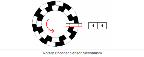
The Rotary Encoder is a device that generates two square wave output signals and a common pin used to determine the rotating position and direction. It works by having a disk with evenly spaced contact zones connected to the common pin and two separate contact pins, A and B.

Pins A and B connect with the common pin as the disk rotates, generating the two square wave output signals. The rotated position can be determined by counting the number of pulses in the signal. However, both signals must be considered simultaneously to determine the rotation direction.
The two output signals are displaced at 90 degrees from each other and are out of phase. If the encoder rotates clockwise, output A is ahead of output B. If the encoder rotates counterclockwise, the output signals have equal values. The rotation direction can be determined by observing the values of the two signals at the time of change, from High to Low or Low to High.

Parts Required
To interface a rotary encoder with an ESP32, you will need the following components:
- ESP32 microcontroller
- Rotary encoder
- Breadboard and jumper wires
Connecting the Components
To connect the components, you will need to follow these steps:
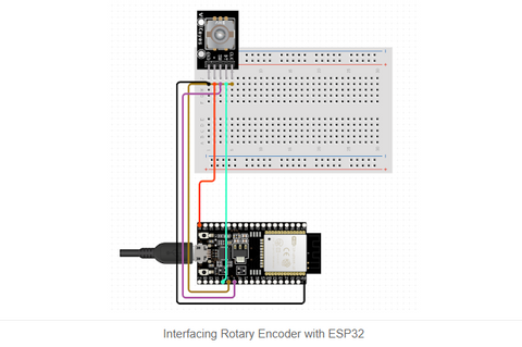
- Connect the power and ground pins of the ESP32 to the power and ground rails of the breadboard. Follow the circuit diagram.
- Connect the two output pins of the rotary encoder to two digital input pins on the ESP32.
- Connect a 10k ohm pull-up resistor between the rotary encoder's output pins and the power rail.
Circuit diagram of ESP32 Rotary Encoder

Programming the ESP32
Once the components are connected, you can begin programming the ESP32 to read the rotary encoder's inputs and perform an action based on the rotation of the shaft. To do this, you will need to use the Arduino Integrated Development Environment (IDE) and write a sketch that implements the following steps:
- Initialize the digital input pins of the ESP32 that are connected to the rotary encoder.
- Read the state of the rotary encoder's output pins.
- Determine the direction of rotation based on the state of the output pins.
- Perform an action based on the direction of rotation, such as adjusting an LED's brightness or controlling a motor's speed.
