
Water Level Sensor Pinout
The working principle of the water level sensor module is very similar to that of a Rain Sensor.
The water level sensor has three pins, runs on 5V power, and gives out the data in analog format. The pinout of the water level sensor is given below:
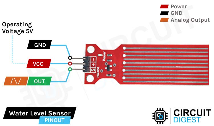
VCC is the power supply pin of the Rain Detection Sensor that can be connected to 5V of the supply.
GND is the ground pin of the board and it should be connected to the ground pin of the Arduino.
OUT is the Analog output pin of the board that will give us an analog signal in between VCC and ground.
How does a Water Level Sensor Work?
The working of the water level sensor is pretty simple and easy to understand. The PCB is made out of long conductive plates. When the water reaches a certain level the conductivity between the two plates changes, and by measuring the changes we can measure the water level.
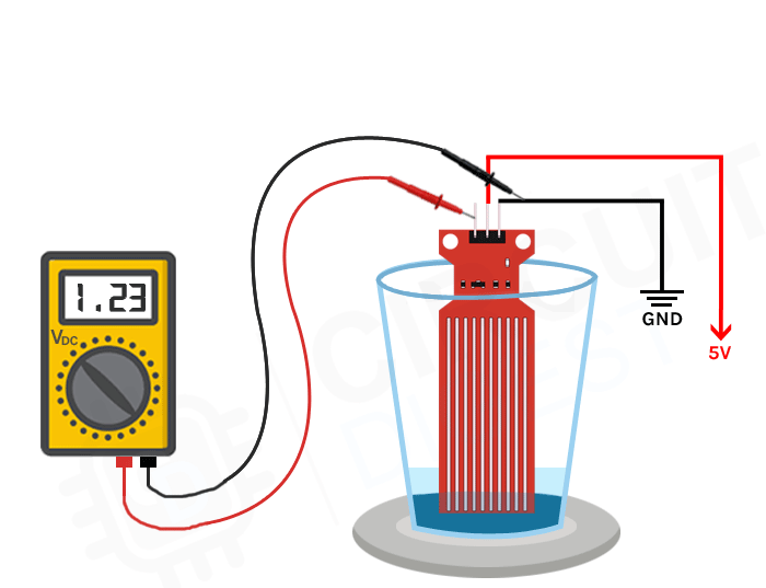
The above Gif shows the working of the water level sensor in action. As you can see when the drop of water falls inside the glass, the water level rises and the voltage on the output pin also rises. This phenomenon is directly proportional to the output voltage. This happens because the sensor portion on the PCB is made out of 10 conducting plates, 5 of which are power tracks and 5 others are the sensor tracks.
Water Level Sensor – Parts
This sensor is very simple, so it can be made with very few parts. This sensor produces the water level and outputs the data in an analog format. The parts marking of the sensor is shown below.
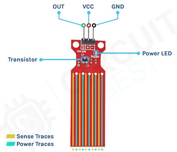
The sensor module has three pins, two of those are power pins and needs to be connected to the 5V and ground pin of the Arduino. As you can see in the above picture, the module has a single power LED that turns on when power is applied to the board, other than that we also have a transistor and a bunch of resistors that in total makes the water level sensor module.
Commonly Asked Questions about Water Level Sensor Module
What are the types of water level sensors?
There are six basic types of commercially used water level indicators: Resistive, Capacitive, Ultrasonic, Frequency, Guided wave GWR, and Pressure transducers. Each of these commonly used indicators have benefits, and each has its drawbacks.
What are level sensors used for?
Water level sensors detect the level of liquids and other fluids and fluidized solids, including slurries, granular materials, and powders that exhibit an upper free surface.
Is it possible to make a water level indicator at home?
If you can accrue all the basic supplies like LEDs, a buzzer, and sensing wires. Then it is not hard to build a basic water level indicator.
Can ultrasonic sensors detect water levels?
With ultrasonic sensors, we can find the water depth calculation by finding the distance between the transceiver and the surface of the water. The sensor will transmit a short ultrasonic pulse, and we can measure the travel time of that pulse (the echo) to the liquid and back.
Circuit Diagram for Water Level Sensor Module
The Schematic Diagram of the Water Level Sensor is shown below and as you can see it's pretty simple to understand.

In the schematic, the collector of the transistor is connected to the supply voltage of 5V, and the emitter is connected to the ground with a 100 Ohms resistor. In the module, a set of 5 conducting plates are connected with the vcc in series with a 100 Ohms resistor and the other 5 sets are connected to the base of the NPN transistor. Now when the water touches these conducting palates, currents start flowing from the 5V supply to the base of the transistor, and the transistor turns on. The more submerged the sensor is, the more output voltage it will generate.
Arduino Water Level Sensor Circuit – Connection Diagram
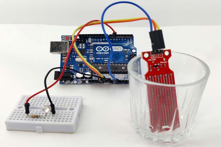
Now that we completely understand how the water level sensor works, we can connect all the required wires to the Arduino UNO board, and in this section of the article, we will discuss just that!
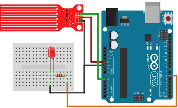
In the above figure, the connection diagram for the water level sensor with Arduino is shown. We have connected an LED to the PWM pin6 of the Arduino board and the analog output pin of the sensor is connected to the A0 pin. The ground pin is common in between the module and the LED, and the VCC is taken from the 5V pin of the Arduino. We will program the Arduino so that the brightness of the LED will change depending on the water level sensed by the sensor.
Working of the Arduino Water Level Sensor
The gif down below shows the Water Level Sensor working. At first, you can see that the LED on the breadboard is off but when we put some water on the glass, the brightness of the LED starts to increase and when the water in the glass is full the LED glows at full brightness.
One problem we have encountered while working with this sensor is that the bottom portion of this sensor is very sensitive, while the top portion is not that sensitive. If the water level crosses the bottom portion, the sensitivity almost goes to maximum and it saturates.