
The HC-SR04 Ultrasonic Distance Sensor
The HC-SR04 Ultrasonic Distance Sensor is an inexpensive device that is very useful for robotics and test equipment projects. This tiny sensor is capable of measuring the distance between itself and the nearest solid object, which is really good information to have if you’re trying to avoid driving into a wall!
The HC-SR04 can be hooked directly to an Arduino or other microcontroller and it operates on 5 volts. It can also be used with the Raspberry Pi, however since the HC-SR04 requires 5-volt logic you’ll need a couple of resistors to interface it with the Pi’s 3.3 volt GPIO port.
This ultrasonic distance sensor is capable of measuring distances between 2 cm to 400 cm (that’s about an inch to 13 feet for those of you who don’t “speak” Metric). It’s a low current device so it’s suitable for battery powered devices. And as a bonus it even looks cool, like a pair of Wall-E Robot eyes for your latest robotic invention!
How the HC-SR04 Works
Ultrasonic distance sensors use pulses of ultrasonic sound (sound above the range of human hearing) to detect the distance between them and nearby solid objects. The sensors consist of two main components:
- An Ultrasonic Transmitter – This transmits the ultrasonic sound pulses, it operates at 40 KHz
- An Ultrasonic Receiver – The receiver listens for the transmitted pulses. If it receives them it produces an output pulse whose width can be used to determine the distance the pulse travelled.
The HC-SR04 has the following four connections:
- VCC – This is the 5 Volt positive power supply.
- Trig – This is the “Trigger” pin, the one driven to send the ultrasonic pulses.
- Echo – This is the pin that produces a pulse when the reflected signal is received. The length of the pulse is proportional to the time it took for the transmitted signal to be detected.
- GND – This is the Ground pin.

The device operates as follows:
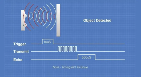
- A 5 volt pulse of at least 10 uS (10 microseconds) in duration is applied to the Trigger pin.
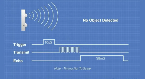
- The HC-SR04 responds by transmitting a burst of eight pulses at 40 KHz. This 8-pulse pattern makes the “ultrasonic signature” from the device unique, allowing the receiver to discriminate between the transmitted pattern and the ultrasonic background noise.
- The eight ultrasonic pulses travel through the air away from the transmitter. Meanwhile the Echo pin goes high to start forming the beginning of the echo-back signal.
- If the pulse in NOT reflected back then the Echo signal will timeout after 38 mS (38 milliseconds) and return low. This produces a 38 mS pulse that indicates no obstruction within the range of the sensor.
- If the pulse IS reflected back the Echo pin goes low when the signal is received. This produces a pulse whose width varies between 150 uS to 25 mS, depending upon the time it took for the signal to be received.
- The width of the received pulse is used to calculate the distance to the reflected object. Remember that the pulse indicates the time it took for the signal to be sent out and reflected back so to get the distance you’ll need to divide your result in half.
One of the most useful sensors for robotics projects is a distance sensor. The HC-SR04 is an inexpensive Ultrasonic Distance Sensor that can assist your robot in navigating around a room. With a bit of care and an additional component it can also be used as a measurement device. In this article you’ll learn everything you need to know to use this wonderful little device with an Arduino.
The HC-SR04 Ultrasonic Distance Sensor
The HC-SR04 Ultrasonic Distance Sensor is an inexpensive device that is very useful for robotics and test equipment projects. This tiny sensor is capable of measuring the distance between itself and the nearest solid object, which is really good information to have if you’re trying to avoid driving into a wall!
The HC-SR04 can be hooked directly to an Arduino or other microcontroller and it operates on 5 volts. It can also be used with the Raspberry Pi, however since the HC-SR04 requires 5-volt logic you’ll need a couple of resistors to interface it with the Pi’s 3.3 volt GPIO port.
This ultrasonic distance sensor is capable of measuring distances between 2 cm to 400 cm (that’s about an inch to 13 feet for those of you who don’t “speak” Metric). It’s a low current device so it’s suitable for battery powered devices. And as a bonus it even looks cool, like a pair of Wall-E Robot eyes for your latest robotic invention!
So read on and I’ll show you how to hook up and use the HC-SR04 Ultrasonic Distance Sensor. We’ll also put it through some tests to see how accurate it is and we’ll look at how we can possibly improve upon that accuracy. And of course I’ll have some sample code and projects for you to try out.
Let’s get started!
How the HC-SR04 Works
Ultrasonic distance sensors use pulses of ultrasonic sound (sound above the range of human hearing) to detect the distance between them and nearby solid objects. The sensors consist of two main components:
- An Ultrasonic Transmitter – This transmits the ultrasonic sound pulses, it operates at 40 KHz
- An Ultrasonic Receiver – The receiver listens for the transmitted pulses. If it receives them it produces an output pulse whose width can be used to determine the distance the pulse travelled.
The HC-SR04 has the following four connections:
- VCC – This is the 5 Volt positive power supply.
- Trig – This is the “Trigger” pin, the one driven to send the ultrasonic pulses.
- Echo – This is the pin that produces a pulse when the reflected signal is received. The length of the pulse is proportional to the time it took for the transmitted signal to be detected.
- GND – This is the Ground pin.

The device operates as follows:
- A 5 volt pulse of at least 10 uS (10 microseconds) in duration is applied to the Trigger pin.
- The HC-SR04 responds by transmitting a burst of eight pulses at 40 KHz. This 8-pulse pattern makes the “ultrasonic signature” from the device unique, allowing the receiver to discriminate between the transmitted pattern and the ultrasonic background noise.
- The eight ultrasonic pulses travel through the air away from the transmitter. Meanwhile the Echo pin goes high to start forming the beginning of the echo-back signal.
- If the pulse in NOT reflected back then the Echo signal will timeout after 38 mS (38 milliseconds) and return low. This produces a 38 mS pulse that indicates no obstruction within the range of the sensor.
- If the pulse IS reflected back the Echo pin goes low when the signal is received. This produces a pulse whose width varies between 150 uS to 25 mS, depending upon the time it took for the signal to be received.
- The width of the received pulse is used to calculate the distance to the reflected object. Remember that the pulse indicates the time it took for the signal to be sent out and reflected back so to get the distance you’ll need to divide your result in half.


The illustration below shows the dimensions of the HC-SR04 Ultrasonic Distance Sensor as well as the effective angle of operation. As you can see the sensor is most accurate when the object to be detected is directly in front of it but you do get a response from objects within a 45 degree “window”. The documentation recommends confining that window to 30 degrees (15 degrees on either side) for accurate readings.

Hooking Up the HC-SR04
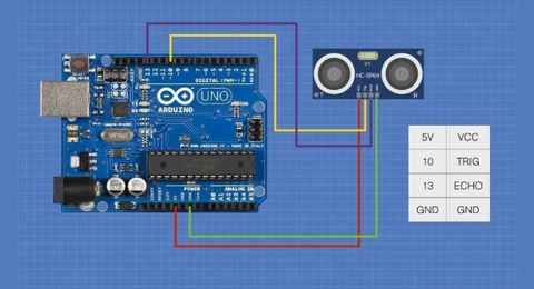
Connecting the HC-SR04 to the Arduino is pretty easy. You’ll need a couple of digital I/O ports and a connection to the Arduino’s 5-Volt and Ground pins.
Actually if you’re short of pins you can even connect both the Trigger and Echo pins of the HC-SR04 to just one digital I/O pin on the Arduino and use code to switch the pin between output (to send the 10 uS pulse) and input (to receive the Echo pulse). Some ultrasonic sensors actually have only one pin that does both Trigger and Echo. I’ll discuss this and give an example further down, so keep reading.
Most of the examples I’ll be showing you here use the more conventional two-pin method. Any Arduino and any digital I/O pins that are free can be used so if you wish to hook it up to a different set of I/O pins then simply change the sketches to reflect those changes. For our demo I’ll use an Arduino Uno and pin 10 for the Trigger and pin 13 for the Echo.
The application notes for the HC-SR04 stress that you need to have the Ground pin connected before you hook up VCC (5-Volts), so if you’re experimenting “live” on a solderless breadboard you might want to keep that in mind.