
Hardware Component
The following components are required to make H-bridge Motor Driver Circuit
| S.no | Component | Value | Qty |
|---|---|---|---|
| 1. | IC | NE555 timer | 2 |
| 2. | Potentiometer | 10k to 100k | 1 |
| 3. | DC motor | 5V | 1 |
| 4. | Battery | 5 – 12V | 1 |
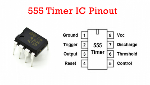
555 IC Pinout
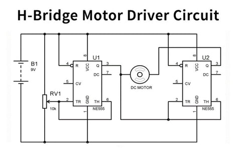
H-bridge Motor Driver Circuit
Working Explanation
Associate the circuit as indicated by the above schematic diagram for the H-bridge motor driver circuit. At the point when we move the 10k pot one way, the DC engine pivots in one direction, and when we move the Pot to inverse heading, then the DC motor likewise turns inversely.
Whereas, when we move the Pot one way the voltage at Trigger PIN 2 goes underneath the Vcc/3, which is the non-inverting input of the Lower comparator inside 555 IC. Henceforth, this sets the OUTPUT of the flip-flop, and 555 carries on as the current source and the other 555 acts as the current sink. Thus, the DC engine turns over pivoting in one direction.
At the point when we move the Pot inversely, the voltage at Threshold PIN 6 goes over the 2/3Vcc, which is the non-inverting input of the Upper comparator inside the 555 IC. Wherefore, this resets the yield of the Flip-flop, and 555 carries on as the Current sink, and simultaneously another 555 goes about as Current source, which pivots the DC engine inversely.
Applications and Uses
An H-bridge utilizes several electronics applications, yet this specific circuit is used to drive a DC motor in a dual direction. The circuit is likewise employed in Robotics.