Introduction to ESP32-S3
ESP32-S3 is a System-on-Chip (SoC) MCU released by Espressif, integrating 2.4 GHz Wi-Fi and Bluetooth 5 (LE) capabilities, including Long Range support. It is equipped with a powerful Xtensa® 32-bit LX7 dual-core processor, clocked at up to 240 MHz, and features 512 KB of built-in SRAM (TCM). Additionally, the chip offers 45 programmable GPIO pins and a wide range of communication interfaces. ESP32-S3 also supports larger high-speed Octal SPI flash and external RAM, enabling users to configure data and instruction caching for improved performance.

ESP32-S3-DevKitC-1 Pinout
The ESP32-S3-DevKitC is a development board based on the ESP32-S3-WROOM-1 module. It is designed to help developers prototype and test their projects with the ESP32-S3 series microcontroller. The board offers a variety of hardware features and pins that can be used to connect peripherals and sensors. Below is an introduction to the pinout of the ESP32-S3-DevKitC:

Pinout Description
| Pin | Description |
|---|---|
| ESP32-S3-WROOM-1 Module | Main module with microcontroller, Wi-Fi, and Bluetooth. |
| USB-UART Bridge | Allows USB communication with ESP32-S3 module. |
| USB Port | Power and serial connection through USB. |
| BOOT Button | Puts ESP32-S3 into bootloader mode for firmware upload. |
| EN Button | Resets the ESP32-S3 module. |
| User Buttons | Two buttons for user-defined purposes. |
| User LEDs | LEDs controlled by the ESP32-S3 for visual feedback. |
| GPIO Pins | General Purpose Input/Output pins for various functions. |
| Analog Input Pins | Pins to read analog signals from sensors. |
| I2C Pins | Pins for I2C communication with sensors. |
| SPI Pins | Pins for high-speed communication with devices. |
| UART Pins | Pins for serial communication with other devices. |
| SD Card Slot | Slot for interfacing with SD cards. |
| JTAG Header | Header for advanced debugging and programming. |
| Power Supply Pins | Pins for 3.3V and GND connections. |
32-bit Xtensa LX7 Processor
Regarding this chip, you may have questions about its integrated Xtensa 32-bit LX7 dual-core processor, as most embedded chips we commonly see are mostly ARM-based. Xtensa is different from ARM cores; the Xtensa LX series processors offer strong reconfigurability and scalability, making them an ideal choice for complex and intensive digital signal processing applications. With Xtensa technology, system design engineers can select the desired unit architecture and create new instructions and hardware execution units to design processor cores that are significantly more powerful than those based on traditional methods. The Xtensa generator can efficiently produce a set of comprehensive software tools, including an operating system, tailored to each processor’s specific combination. The customizable nature of Xtensa processors allows for great flexibility in design and high efficiency, making them the optimal choice for all highly synthesized single-chip systems. By employing a combination of hardware reconfigurability and software programming, Xtensa processors not only enhance computational performance but also offer ease of implementation for control purposes.

Applications of ESP32-S3
The low-power chip ESP32-S3 is specifically designed for Internet of Things (IoT) devices and has a wide range of applications. It’s safe to say that almost all consumer electronic products on the market today can use it. For example, household appliances like air conditioners or rice cookers can be equipped with it to enable remote control and connectivity. Some specific application areas include:
- Smart Home Appliances
- Universal Low Power IoT Sensor Hub
- Automated Industry
- Universal Low Power IOT Data Logger
- Medical Insurance
- Camera Video Streaming
- Consumer Electronics
- USB Device
- Smart Agriculture
- Speech Recognition
- POS Machine
- Image Identification
- Service Robot
- Wi-Fi + Bluetooth Network Card
- Audio Equipment
- Touch and Proximity Sensing
ESP32-S3 Vs STM32
The ESP32-S3 stands as an evolution in chip design compared to the STM32 series. While the STM32 chips have a well-established reputation and are widely used in various applications, the ESP32 series has strategically positioned itself ahead of the curve. By integrating WiFi and Bluetooth functionalities directly into the System-on-Chip (SoC), the ESP32-S3 caters to the growing demand for smart and connected devices in the IoT era.
While the STM32 chips are powerful and versatile microcontrollers, they may require additional components or modules to enable WiFi and Bluetooth connectivity. In contrast, the ESP32-S3 offers the convenience of built-in wireless communication, reducing the need for external components and simplifying the design process for IoT applications. A comparison of the functional diagrams of the ESP32-S3 and STM32F103XX would reveal this advancement.
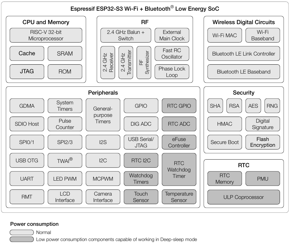
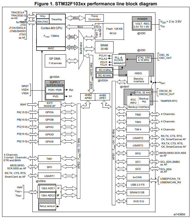
Espressif’s decision to equip the ESP32 with WiFi and Bluetooth capabilities from the start has allowed them to tap into emerging trends and address the changing needs of the electronics industry. With the increasing importance of internet connectivity and wireless communication, the ESP32-S3’s built-in features align perfectly with the demands of modern electronic products.
Moreover, the ESP32-S3 series not only offers WiFi and Bluetooth but also boasts improvements in performance, power efficiency, and ease of use. Although the STM32 series may still have certain advantages in terms of raw performance and stability, the ESP32-S3 is quickly catching up and has already gained popularity in various IoT and connected devices applications.
Making Microcontroller Board with ESP32-S3
To apply the ESP32-S3 chip to practical products, it needs to be packaged and supplemented with peripheral circuits and communication IO ports for external device communication. For instance, to create a facial recognition access control device, a camera interface is required to connect an external camera for image acquisition and processing, an antenna circuit for WiFi or Bluetooth connectivity, and an SPI flash for storing large amounts of data. The following figure is the official schematic diagram of the circuit, which generally includes about 20 resistors, capacitors, inductors, a passive crystal oscillator and an SPI flash.
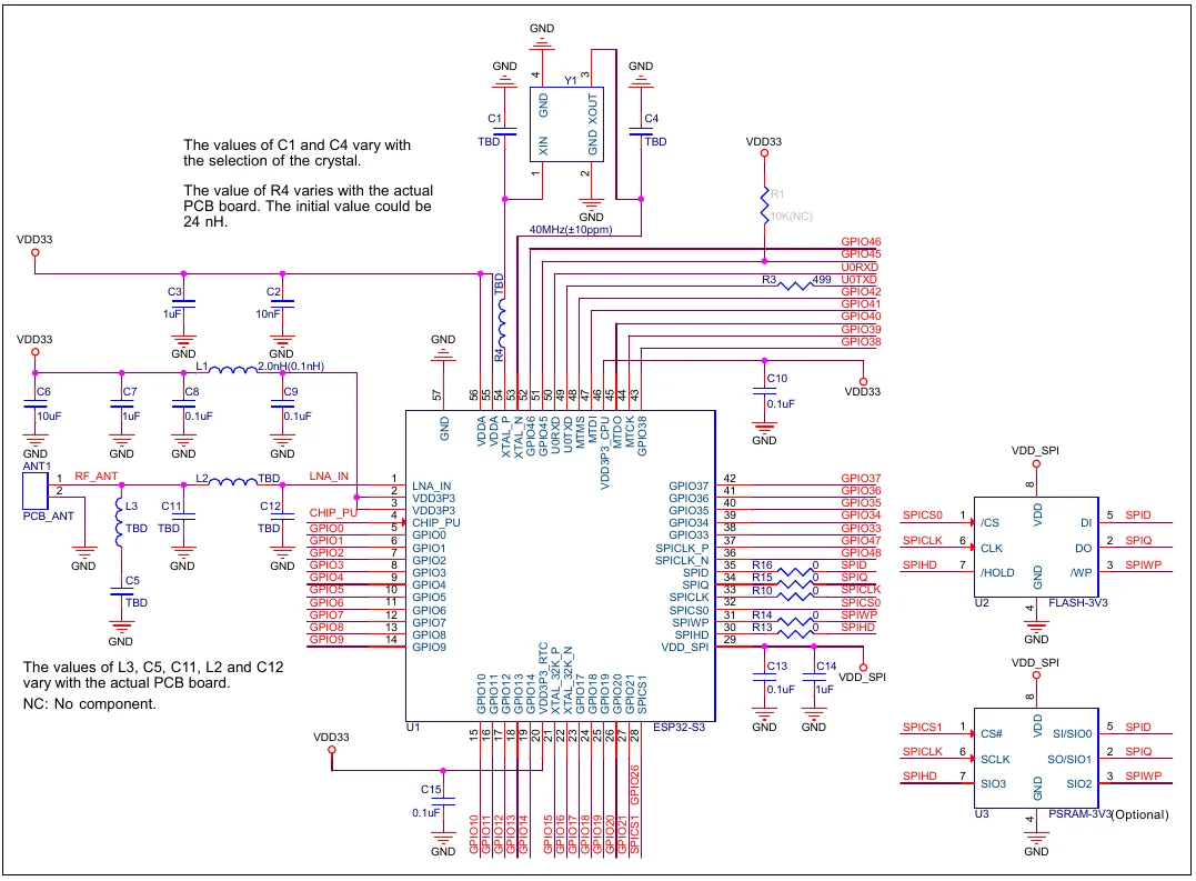
If you find designing these circuits challenging, you can opt for pre-designed and packaged ESP32-S3 modules. Using modules can shorten our development cycle, but it may come at a higher cost. Alternatively, we can develop modules following the official schematic provided by Espressif. The modules officially released by Espressif are shown in the following image.
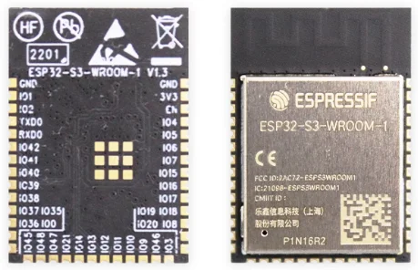
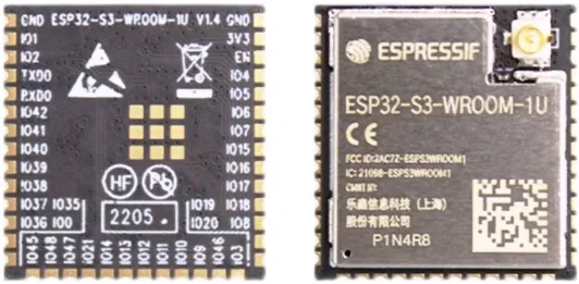
The modules released by Espressif will have different models. In fact, the core chip is the same as ESP32-S3. The difference between different models lies in the size of off-chip Flash and PSRAM. The model with the highest configuration officially released is ESP32-S3- WROOM-1-N16R8, it has 16MB of Flash and 8MB of PSRAM, I think this configuration is enough for our development:
| Model | Flash2 | PSRAM | Ambient temperature (℃) | Module size (mm) |
|---|---|---|---|---|
| ESP32-S3-WROOM-1-N4 | 4 MB (Quad SPI) | - | -40~85 | 18.0 * 25.5 * 3.1 |
| ESP32-S3-WROOM-1-N8 | 8 MB (Quad SPI) | - | -40~85 | 18.0 * 25.5 * 3.1 |
| ESP32-S3-WROOM-1-N16 | 16 MB (Quad SPI) | - | -40~85 | 18.0 * 25.5 * 3.1 |
| ESP32-S3-WROOM-1-H4 | 4 MB (Quad SPI) | - | -40~105 | 18.0 * 25.5 * 3.1 |
| ESP32-S3-WROOM-1-N4R2 | 4 MB (Quad SPI) | 2 MB (Quad SPI) | -40~85 | 18.0 * 25.5 * 3.1 |
| ESP32-S3-WROOM-1-N8R2 | 8 MB (Quad SPI) | 2 MB (Quad SPI) | -40~85 | 18.0 * 25.5 * 3.1 |
| ESP32-S3-WROOM-1-N16R2 | 16 MB (Quad SPI) | 2 MB (Quad SPI) | -40~85 | 18.0 * 25.5 * 3.1 |
| ESP32-S3-WROOM-1-N4R8 | 4 MB (Quad SPI) | 8 MB (Octal SPI) | -40~65 | 18.0 * 25.5 * 3.1 |
| ESP32-S3-WROOM-1-N8R8 | 8 MB (Quad SPI) | 8 MB (Octal SPI) | -40~65 | 18.0 * 25.5 * 3.1 |
| ESP32-S3-WROOM-1-N16R8 | 16 MB (Quad SPI) | 8 MB (Octal SPI) | -40~65 | 18.0 * 25.5 * 3.1 |
Design Expansion Board with ESP32-S3
Not all development boards need to design expansion boards, you only need to design the corresponding external interfaces directly when designing the development board. But this will cause a problem. If we need to make other products, the entire development board needs to be redesigned, which will cause some waste of time and hardware costs. My idea is that our core development board remains unchanged, and we can design some expansion boards with corresponding interfaces according to product needs, so that our development time will be much faster, because it is very easy to design external interface boards. Another reason is that if some functions on our core board fail and cannot be repaired, we only need a better core board, and we don’t need to make any changes to the expansion boards connected to external devices.
