Components Required
- ESP32 CAM Module
- USB to UART TTL Serial converter/ FTDI module
- Connecting Wires
- External 5v power Supply
ESP32 CAM Module
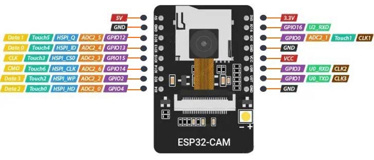
The ESP32-CAM module (developed by AI-Thinker) uses an ESP32 microcontroller with an OV2640 camera sensor which comes with support for Wi-Fi and Bluetooth connectivity, some of the key specifications are:
- Microcontroller: ESP32-D0WDQ6, dual-core 32-bit, up to 240 MHz clock speed.
- Camera: OV2640, 2MP resolution (1600x1200 pixels).
- Memory: 4 MB Flash, approximately 520-600 KB RAM, and external 8MB PSRAM.
- Supports SD card reader up to 4GB.
- The ESP32-S chip offers a total of 32 GPIO pins; however, since a significant number of them are reserved for internal use, the ESP32-CAM module offers only 10 available GPIO pins. Despite this limitation, these pins are versatile and are used for interfacing UART, SPI, I2C, PWM, ADC, DAC, and Touch functionalities, making the ESP32-CAM a powerful and flexible platform for various applications.
- Power Pins include 5v & 3.3v. It has an inbuilt 3.3 voltage regulator.
FTDI Module
Since the ESP32 CAM board does not have a USB to TTL serial converter IC. Hence the only option left behind is to use the FTDI module to program the ESP32 board using a PC. The below diagram gives you an idea about its pinout & its interfaces.
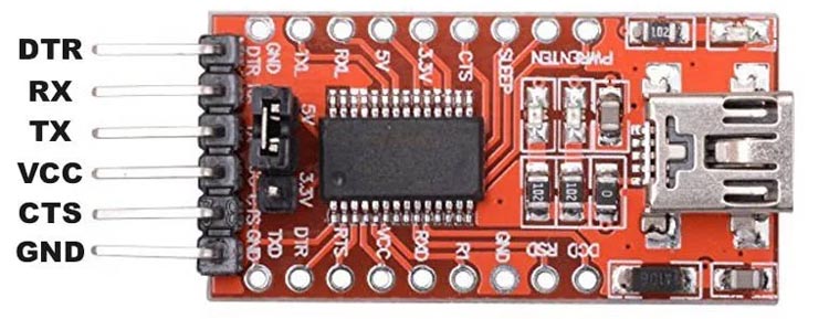
Generally, the module has Six pins to communicate with the microcontrollers.
GND: Ground pin
5V: Output for 5V version, input for 3.3V version
TXD: Transmit Data (Output from module)
RXD: Receive Data (Input to the module)
CTS: Clear to Send (Input to the module)
DTR: Data Terminal Ready (Output from module)
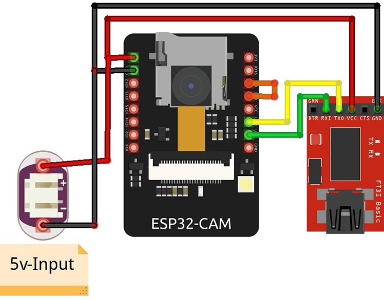
ESP32 CAM and FTDI Programmer Circuit Diagram
The Serial Communication Technique is used to program the ESP32 Cam using FTDI (USB-to-UART) module. The FTDI module acts as a serial converter between the computer's USB to the UART interface for the ESP-32 CAM, allowing you to upload code and interact with the module.
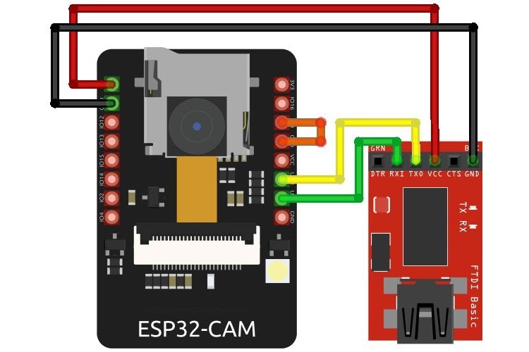
By following the connection diagram, you can connect the ESP32-CAM with an FTDI module for programming:
- Connect GND on the FTDI module to GND on the ESP32-CAM.
- Connect RX on the FTDI module to U0TXD on the ESP32-CAM.
- Connect TX on the FTDI module to U0RXD on the ESP32-CAM.
- Connect VCC on the FTDI module to the 5V power pin on the ESP32-CAM.
Important: Sort the GPIO0 to GND of the ESP32-CAM to put the board in boot mode for programming. Later On, necessarily needs to remove the sorting after the successful uploading of the program.
In certain ESP32-CAM boards, you may encounter a brown-out detector error, which is typically caused by an insufficient power supply from the FTDI (USB to UART) module. To address this issue, it is recommended to connect an external 5V power supply directly to the ESP32-CAM board. This external power supply will ensure the ESP32-CAM receives adequate voltage and can operate without triggering the brown-out detector error as shown below diagram:
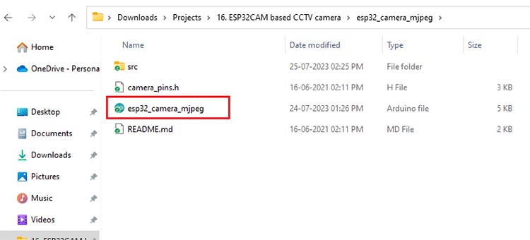
Arduino Code for Programming ESP32-CAM CCTV Camera
We will use Arduino IDE to program our development board. The program sets the various interfacing pins for the camera module and created a web-based streaming link that will be used to stream on VLC.