

Overview : PCB Design Process
The following image shows the basic PCB layout and design steps.
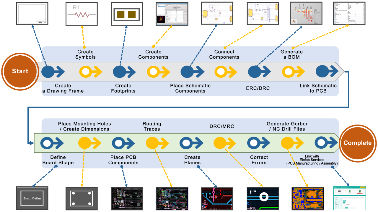
How to Design a PCB Layout
Creating a Drawing Frame
Creating a Schematic Symbol
Creating a PCB Footprint
Creating a Component
Placing Schematic Components
Wiring
Verifying Your Schematic Design with ERC/DRC
Generating a BOM File
Linking the Schematic to the PCB
Defining the Board Size
Placing Mounting Holes
Placing Dimensions
Placing Components