History of Seven Segment Displays
The seven segment display dates back to century old. In the year 1908 F.W. Wood invented eight segment displays which displays the digit ‘4’ by using diagonal bar. After that in 1910 seven segment display is invented and is illuminated using incandescent bulbs .They are used in electric power plants but has gained no much reputation.
Later in 1970’s, with the advent of LEDs usage of seven segment displays increased to a large extent.
Pin Diagram Seven of Segment Display
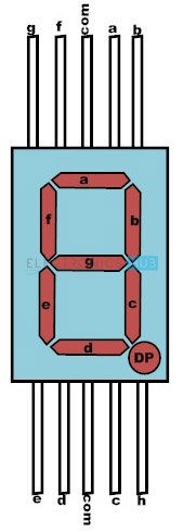
Generally seven segment displays are available in 10 pin package. The pin diagram of seven segment display is shown in the above figure. Seven segment display is an electronic circuit consisting of 10 pins.
Out of 10 pins 8 are LED pins and these are left freely. 2 pins in middle are common pins and these are internally shorted. Depending on either the common pin is cathode or anode seven segment displays can be either named as common cathode or common anode display respectively.
These are available from different vendors .They have shape of rectangular box similar to that of IC but in large size.
Top and Bottom View of Seven Segment Display
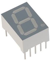
From top view 8 segments can be seen (7 display segments and one decimal point) in the form of numeral ‘8’.
Here, the 7 LED’s called segments are assigned with an alphabet from A to G. Forward biasing the particular segment or LED will emit the light energy thus illuminating a part of numeral. There is another segment assigned as H, used for displaying dot.
The decimal or dot point is used for representing the decimal point in a numeral. For example to display 2.5, dot is used to represent the decimal point in this numeral.
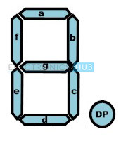 Generally, in LED package either all the cathodes or all anodes of the segments are combined to form a common pin. Thus each seven segment display will have seven pins used for displaying the digits, one common pin and another pin for decimal/dot point
Bottom view of the seven segment display is shown below. The bottom view of the segment shows 10 pins of the segment. These are cathode or anode pins of the LEDs present in the seven segment. Seven segment is illuminated using these pins.

Internal Structure of Seven Segment Display
The internal structure of display is very hard. Internally, the device will have SMD LEDs. This can be divided into two parts i.e. internal circuit and the display. The internal circuit will have LEDs arranged in the rectangular form. These two parts are surrounded by glass, ceramics and plastic in order to protect them.
Working of Seven Segment Display
Seven segment display works, by glowing the required respective LEDS in the numeral. The display is controlled using pins that are left freely. Forward biasing of these pins in a sequence will display the particular numeral or alphabet. Depending on the type of seven segment the segment pins are applied with logic high or logic zero and in the similar way to the common pins also.
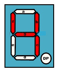
For example to display numeral ‘1’ segments b and c are to be switched on and the remaining segments are required to be switched off. In order to display two digits two seven segments are used.
Depending on either the common pin is anode or cathode, seven segments are divided into following types.
Types of Seven Segment Displays
The following are the types of seven segments.
- Common Anode (CA)
- Common Cathode (CC)
1. Common Anode Seven Segment Display
In common anode type, all the anodes of 8 LED’s are connected to the common terminal and cathodes are left free. Thus, in order to glow the LED, these cathodes have to be connected to the logic ‘0’ and anode to the logic ‘1’.

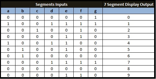
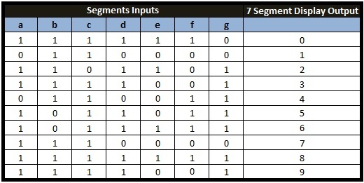
Below truth table gives the information required for driving the common anode seven segments.
In order to display zero on this segment one should enable logic high on a, b, c, d, e and f segments and logic low on segment ‘g’. Thus, the above table provides data on seven segments for displaying numerals from 0-9.
2. Common Cathode Seven Segment Display
As the name indicates cathode is the common pin for this type of seven segments and remaining 8 pins are left free. Here, logic low is applied to the common pin and logic high to the remaining pins.

Truth Table: The truth table of seven segment display is shown below.
Above truth table shows the data to be applied to the seven segments to display the digits. In order to display digit‘0’ on seven segment , segments a , b , c , d , e and f are applied with logic high and segment g is applied with logic low.
Driving a Seven Segment Display
A seven segment display can be driven using resistors, transistors and IC’s. But mostly the driving is done by the integrated circuits because of their ease co-operation.
Necessity for Driving Seven Segments
Seven segment devices are generally made up of LEDs. These LEDs will glow when they are forward biased. Intensity of the LEDs depends on forward current. So, sufficient forward current has to be provided to these LEDs to glow with full intensity. This is provided by the driver and is applied to the seven segments. The following methods are practised to drive the seven segments.
Driving a Seven Segment Display with Resistor
Driving a seven segment using resistor is the most common method. In this, generally we use the resistor as the driving element. Generally, LED requires 20 milli Amps of current. Current more than this value may damage the LED. To limit this current a resistor is used .This is called current limiting resistor. Circuit is as shown below.

Segment pins of the seven segment are connected using a resistor and a switch. The 8 switches are connected to the 8 current limiting resistors and they are connected to a to g segments of display. Let us see how this circuit drives the digital display.
To glow the segment ‘a’, close the switch ‘a’. The current passes through resistor and some drop occurs at current limiting resistor. Thus, the sufficient current passes to the LED. Suppose to display digit 7 switches a, b, c are closed. But the disadvantage here is, illuminating all the LEDs at a time reduces the current.
Driving a Seven Segment Display with Transistor
Another way of driving the seven segments is through transistor. In this, transistor is used for amplifying the input current. The collector of the transistor is connected to the common pin of the seven segment, emitter is connected to the ground and base is connected Vcc. The transistor connected to the common pin amplifies the current in the seven segment.

Driving a Seven Segment Display with Integrated Circuit
Another way of driving the seven segments is through integrated circuits. This is generally called as seven segment driver or decoder. The most frequently used decoder is 4511. This is a CMOS chip which converts 4 bit binary coded decimal to 8 bit seven segment data. CMOS seven segment decoder connected to the seven segments is shown below.

The above figure shows driving of a seven segment display using BCD to seven segment decoder. Here we have to give BCD data as input to display digits 0 to 9. For example, to display the digit 7 the input to be applied is 0111.
The decoder decodes the applied BCD input and sends the appropriate output to the segments. The decoder outputs are connected to the seven segment inputs through the resistors. These resistors are used to limit the current.
Applications of Seven Segment Displays
- The applications of seven segments are mostly in digital calculators, electronic meters, digital clocks, odometers, digital clocks, clock radios, etc.
- Today most of the 7 segment applications are using LCDs, because of low current consumption.

