Multi mode audio amplifier circuit
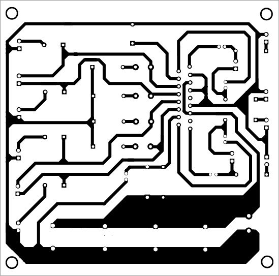
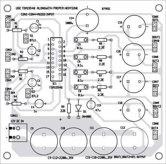
The circuit of the simple 4-channel multi mode audio amplifier is shown in Fig. 1. It has four channels and each channel can provide around 11W over a load of 2-ohms and around 6W over a load of 4-ohms. The circuit will also work with loads of 4-ohms to 16-ohms.
Mode selection
The multi-mode function includes single-channel and bridge-tied load (BTL) modes. These are controlled using switches S1 and S2. In bridge mode, output power can be around 22W on a 4-ohm load with a good heat-sink, power supply and montage.
Gain of each channel is fixed at 20dB in single-channel mode and 26dB in BTL mode.
Input resistance of each channel of TDA1554Q amplifier (IC1) is around 60-kilo-ohm. When two or four inputs are paralleled, resistance is reduced by two or four times. Consequently, input capacitors C1 through C4 should have enough capacity to give the required sound in the low-frequency range.
