Components Required:
- Transformer 12V 1Amp
- IC LM317 (2)
- Diode Bridge W005
- Connector Terminal Block (2)
- Capacitor 1000uF, 1uF
- Capacitor 0.1uF (5)
- Variable resistor 100R
- Resistor 1k (5)
- Resistor 10k
- Diode- Nn007 (3)
- LM358 – Opamp
- 0.05R - Shunt Resistor/wire
- LCD-16*2 (optional)
- Arduino Nano (optional)
Circuit Explanation:
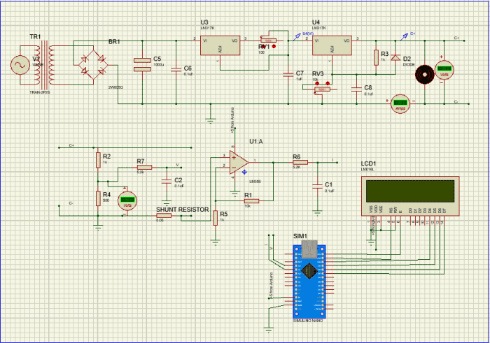
The complete schematics of this Battery Charger Circuit are shown below:

The main objective of our 12V power supply circuit is to control the voltage and current for the battery so that it can be charged in the best possible way. For this purpose we have used two LM317 ICs, one is used to control the voltage and the other is used to limit the current. Here, in our circuit the IC U1 is used to control the current and the IC U3 is used to control the voltage. I would strongly recommend you to read the datasheet of LM317 and understand it, so that it comes in handy while trying similar projects since LM317 is a most used Variable regulator.
Voltage Regulator Circuit:
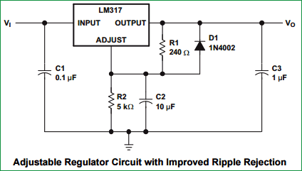
A simple Voltage Regulator Circuit, taken from LM317’s datasheet, is shown in the figure above. Here the output voltage is decided by the resistor values R1 and R2, in our case the resistor R2 is used as a variable resistor to control the output voltage. The formulae to calculate the output voltage is Vout = 1.25 (1+R2/R1). Using this formulae, the value of resistance 1K (R8) and 10K – pot (RV2) is selected. You can also use this LM317 calculator to calculate the value of R2.
Current Limiter Circuit:
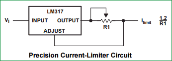
The Current Limiter Circuit, taken from LM317’s datasheet, is shown in the above figure; this is a simple circuit which can be used to limit the current in our circuit based on the resistance value R1. The formulae to calculate the output current is Iout= 1.2/R1. Based on these formulae the value of pot RV1 is selected as 100R.
Hence, in order to control the current and voltage two potentiometers RV1 and RV2 are used respectively as shown in the schematics above. The LM317 is powered by a diode bridge; the Diode Bridge itself is connected to a Transformer through connector P1. The rating of the transformer is 12V 1 Amps. This circuit alone is sufficient for us to make a simple circuit, but with help of few additional set up we can monitor the current and voltage of our charger on LCD, which is explained below.
Display Voltage and Current on LCD using Arduino:
With the help of an Arduino Nano and an LCD (16*2), we can display the voltage and current values of our charger. But, how can we do this!!
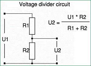
Arduino Nano is 5V operational Microcontroller, anything more than 5V will kill it. But, our charger works on 12V, hence with the help of a Voltage divider circuit the value of (0-14) Volt is mapped down to (0-5)V using resistor R1 (1k) and R2 (500R), like have previously done in 0-24v 3A Regulated Power Supply Circuit, to display the Voltage on LCD using Arduino Nano.
To measure the current we use a shunt resistor R4 of very low value to create a voltage drop across the resistor, as you can see in the circuit below. Now using Ohms Law calculator we can calculate the current passing through the resistor using the formulae I=V/R.


In our circuit the value of R4 is 0.05R and the maximum current that can pass through our circuit will be 1.2 Amps because the transformer is rated so. The power rating of the resistor can be calculated using P=I^2 R. In our case P=(1.2*1.2*0.05) => 0.07 which is less than a quarter watt. But if you do not get a 0.05R or if your current rating is higher, then calculate the Power accordingly. Now if we are able to measure the voltage drop across the resistor R4, we would be able to calculate the current through the circuit using our Arduino. But, this voltage drop is very minimal for our Arduino to read it. Hence an Amplifier circuit is constructed using Op-amp LM358 as shown in the figure above, the output of this Op-Amp is given to our Arduino through an R-C circuit to measure the current and display in on the LCD.
Once we decide our value of components in our circuit, it is always recommended to use simulation software to verify our values before we proceed with our actual hardware. Here, I have used Proteus 8 to simulate the circuit as shown below. You can run the simulation using the file (12V_charger.pdsprj) given in this zip file.